
Intelligent control panel switch for illuminating lamp

A technology of intelligent control and panel switch, applied in the direction of energy-saving control technology, electrical components, chassis/cabinet/drawer parts, etc., can solve the problems of single panel switch control function, single control function, and inability to perform conversion, etc. To achieve the effect of extensive use, complete functions and strong stereoscopic effect

Pending Publication Date: 2021-02-05
杭州帕诺迩照明科技有限公司
View PDF0 Cites 0 Cited by
  • Summary
  • Abstract
  • Description
  • Claims
  • Application Information

AI Technical Summary

Problems solved by technology

[0002] Lighting appliances are an indispensable part of life; with the development of society, people have higher and higher requirements for the intelligence of lamps and lanterns. Some existing lamps already have the function of switching light colors, which are basically completed by remote control and voice control. Part of the command, the control function is relatively simple; however, the existing panel switch control function is still relatively simple, can only play a role of opening or closing, and cannot complete the control of some intelligent lamps; for example, the light brightness adjustment of the ceiling lamp, the light Color switching, etc.; at the same time, the existing panel switch needs to be slotted on the wall during installation, which requires a large amount of work and high cost. There are limitations, and there are certain safety hazards; therefore, it is necessary to improve the existing panel switch installation mode, and at the same time improve the intelligence of the panel switch to make the panel switch multi-functional, so as to meet the control requirements of multi-functional lamps

Method used


Image

  • Intelligent control panel switch for illuminating lamp
  • Intelligent control panel switch for illuminating lamp
  • Intelligent control panel switch for illuminating lamp

Examples


Embodiment Construction

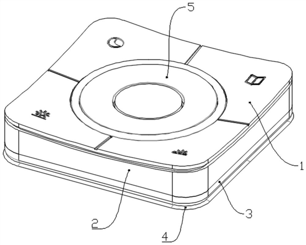
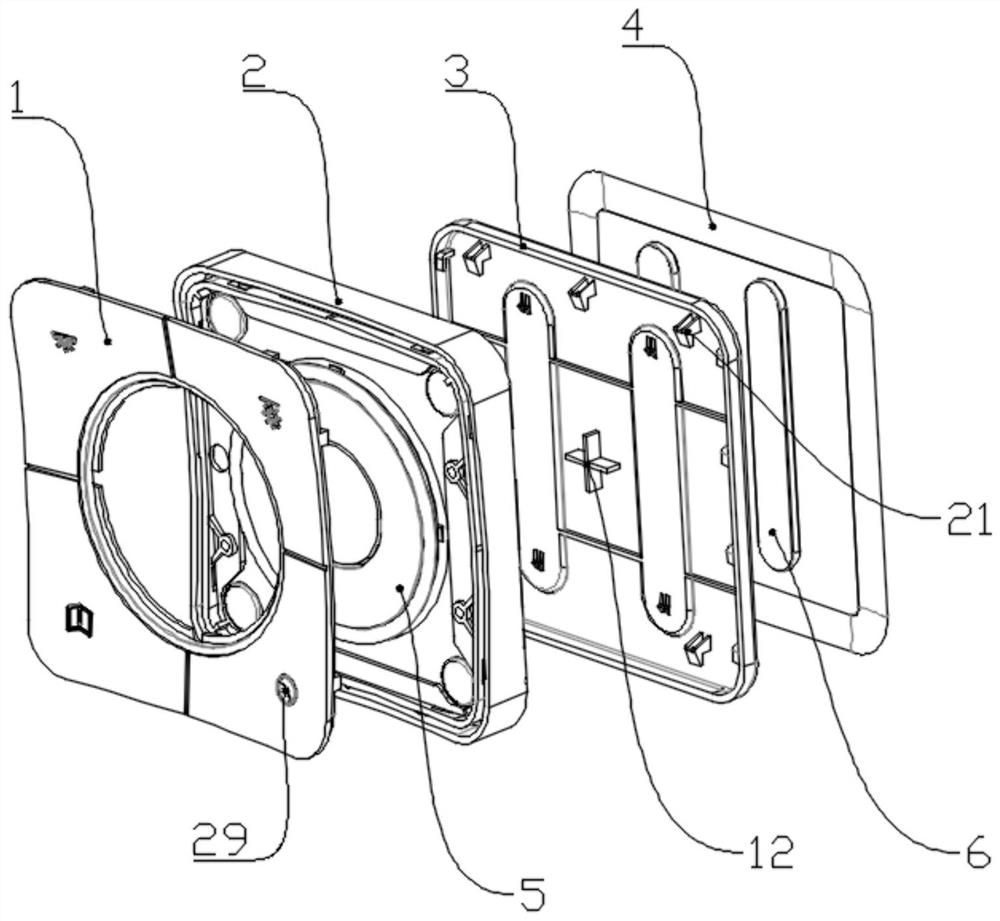
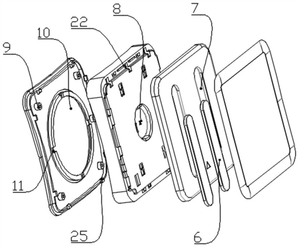
[0030] refer to Figure 1 to Figure 5 The shown intelligent control panel switch for lighting lamps includes panel 1, base frame 2, base 3, metal sheet 4, rubber pad 5, inner frame 13 and PCB board 15, panel 1, inner frame 13, rubber pad 5 , PCB board 15, base frame 2, base 3, and metal sheet 4 are sequentially connected, and the rubber pad 5 and PCB board 15 are arranged between the inner frame 13 and the base frame 2, and the inner frame 13 is embedded in the base frame 2, and the panel 1 is fixed on the inner frame 13, the surface of the panel 1 is an arc-shaped surface structure with four corners raised, and four functional areas are formed, each functional area is provided with a concave-convex mark 29, and the middle of the panel 1 is set There is a round hole 10, and a positioning groove 11 is arranged around the round hole 10. The middle of the rubber pad 5 protrudes outward to form two ring-shaped bosses inside and outside, and the ring-shaped bosses are embedded in t...


PUM


Abstract

An intelligent control panel switch for an illuminating lamp is disclosed in the invention, and comprises a panel, a base frame, a base, a metal sheet, a rubber pad, an inner frame and a PCB, the panel, the inner frame, the rubber pad, the PCB, the base frame, the base and the metal sheet are connected in sequence, the rubber pad and the PCB are arranged between the inner frame and the base frame,and the inner frame is embedded into the base frame. The panel is fixed on the inner frame, the surface of the panel is of an arc-shaped surface structure with four tilted corners, four functional areas are formed, concave-convex marks are arranged on the functional areas, and the middle of the rubber pad protrudes outwards to form an inner annular boss and an outer annular boss. The switch is convenient to install, does not need to be slotted in the installation process, is complete in function and high in practicability, can meet the requirements of the intelligent lighting lamp, can switchand adjust the light intensity, color and various working modes of the lighting lamp, and is novel in appearance design and good in hand feeling.

Description

technical field [0001] The invention relates to an intelligent control panel switch for lighting fixtures. Background technique [0002] Lighting appliances are an indispensable part of life; with the development of society, people have higher and higher requirements for the intelligence of lamps and lanterns. Some existing lamps already have the function of switching light colors, which are basically completed by remote control and voice control. Part of the command, the control function is relatively simple; however, the existing panel switch control function is still relatively simple, can only play a role of opening or closing, and cannot complete the control of some intelligent lamps; for example, the light brightness adjustment of the ceiling lamp, the light Color switching, etc.; at the same time, the existing panel switch needs to be slotted on the wall during installation, which requires a large amount of work and high cost. There are limitations, and there are cer...

Claims


Application Information

Patent Timeline
Patent Type & Authority Applications(China)
IPC IPC(8): H05B47/17H05K5/02
CPCH05B47/17H05K5/0204H05K5/0217Y02B20/40
Inventor 陈和生陈耀卫
Owner 杭州帕诺迩照明科技有限公司
Learn More