
Four-way casing quick-mounting structure applied to oil well

A casing and oil well technology, which is applied in the field of spool casing quick-installation structure, can solve the problems of manual disassembly and assembly, reduce the assembly speed of spool casing, and difficulty in flange sealing connection, etc. The effect of the simple process of connection, guaranteed connection, installation and removal

Active Publication Date: 2021-02-05
临沂金良不锈钢制品有限公司
View PDF6 Cites 1 Cited by
  • Summary
  • Abstract
  • Description
  • Claims
  • Application Information

AI Technical Summary

Problems solved by technology

[0003] However, the connection of existing casings connected by flanges is very cumbersome, and it takes a lot of time to disassemble and assemble manually, which reduces the assembly speed of the four-way casing, and the sealing connection of flanges is difficult, and construction personnel cannot When assembled correctly, will reduce the tightness between the bushings

Method used


Image

  • Four-way casing quick-mounting structure applied to oil well
  • Four-way casing quick-mounting structure applied to oil well
  • Four-way casing quick-mounting structure applied to oil well

Examples


Embodiment 1

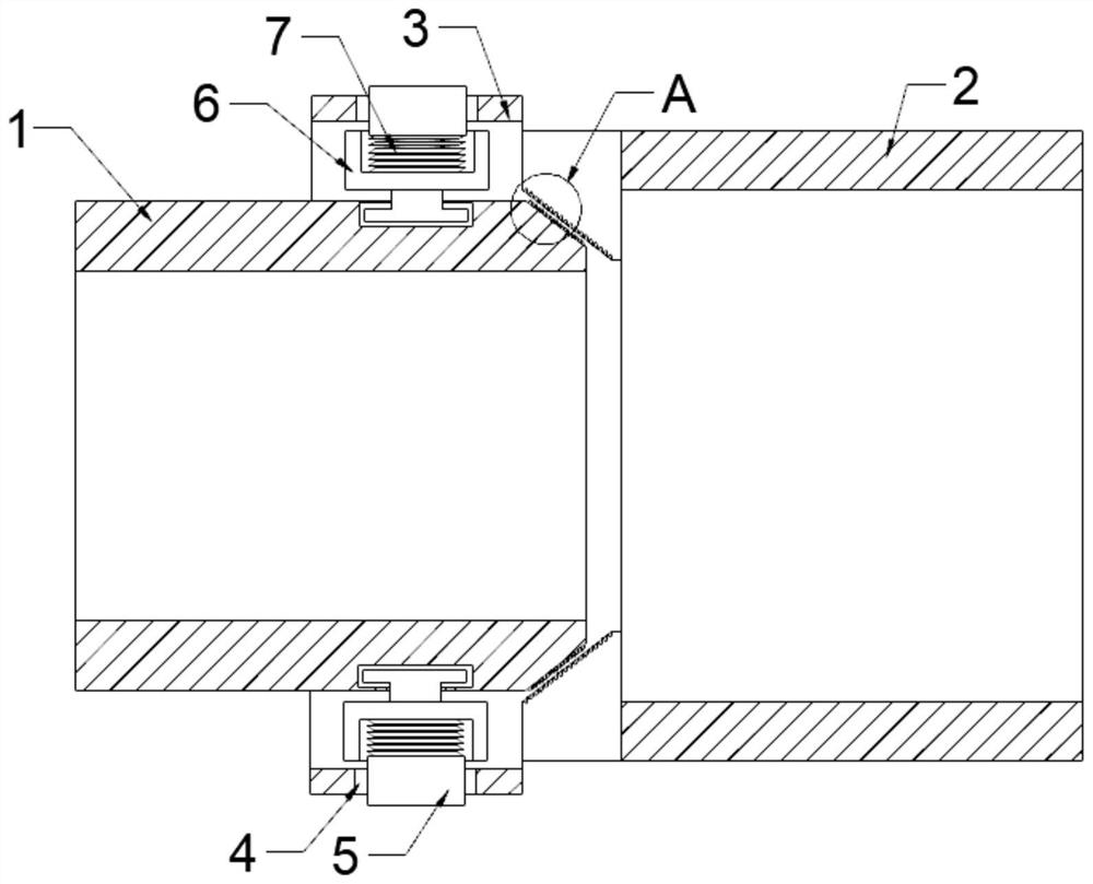
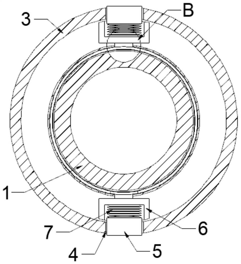
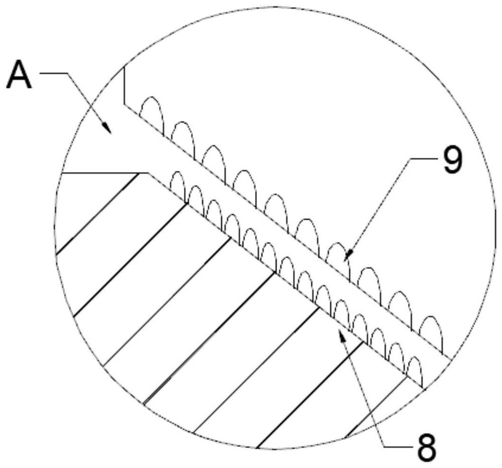
[0034] refer to Figure 1-4 , a four-way casing quick-installation structure applied to oil wells, the four-way casing quick-installation structure includes:

[0035] The sleeve body, the sleeve body includes the first sleeve 1, the second sleeve 2 and the connecting pipe 3, the diameter of the second sleeve 2 is larger than the diameter of the first sleeve 1, and the first sleeve 1 is connected to the second sleeve through the connection mechanism. The pipe 2 is connected, the connecting pipe 3 is fixedly connected with the end of the second casing 2 close to the first casing 1, and the diameter is larger than the second casing 2, and the connecting pipe 3 is sleeved on the first casing 1;

[0036] The limit mechanism, the limit mechanism includes a limit port 4, a limit block 5, a mounting block 6 and a spring 7, two limit ports 4 are set at the opposite ends of the connecting pipe 3, and two mounting blocks 6 are provided with installation slot, and is slidably installed o...

Embodiment 2

[0044] refer to Figure 5-7 The difference between this embodiment and the first embodiment is that the connecting pipe 3 and the first sleeve 1 are fixedly connected by a reinforcement mechanism, and the reinforcement mechanism includes a bayonet 13, a bayonet 14 and a fixing rod 15, and the two bayonets 13 are opposite to each other. It is set on both sides of the connecting pipe 3, and the connecting line of the bayonet 13 is perpendicular to the connecting line of the limit port 4, the slot 14 is oppositely set on the surface of the first casing 1, and the fixing rod 15 is set inside the bayonet 13 and the slot 14 ;

[0045] The side wall of the fixed rod 15 is provided with a plurality of strip grooves 16, and the inside of the strip groove 16 is fixedly connected with a support foot 17. The support foot 17 is made of an elastic material, and the expanded width is greater than the diameter of the limit port 4, and the strip groove 16 is to have a place to place the brace...


PUM


Abstract

The invention discloses a four-way casing quick-mounting structure applied to an oil well. The four-way casing quick-mounting structure comprises a casing main body and a limiting mechanism, the casing main body comprises a first casing, a second casing and a connecting pipe, the diameter of the second casing is larger than that of the first casing, the first casing is connected with the second casing through a connecting mechanism, the connecting pipe is fixedly connected with the end, close to the first casing, of the second casing, the first casing is sleeved with the connecting pipe, the limiting mechanism comprises limiting openings, limiting blocks, mounting blocks and springs, the two limiting openings are formed in the two opposite ends of the connecting pipe, mounting grooves areformed in the two mounting blocks, the two ends of the springs are fixedly connected with the bottoms of the mounting grooves and the bottoms of the limiting blocks correspondingly, and the limiting blocks are matched with the limiting openings and the mounting grooves in size and shape. By means of the connecting mode of the structure, the mounting and dismounting processes are simple and convenient, operation is easy, and constructors can complete mounting and dismounting with bare hands.

Description

technical field [0001] The invention relates to the technical field of glass cleaning, in particular to a four-way casing quick-installation structure applied to oil wells. Background technique [0002] In the oil production operation, the casing spool, as the main part of tubing and casing gathering and diverting, plays a key role in the structural stability of the entire oil production device. The lower part is connected to the suspension casing to seal the annular space of the oil casing. At present, the connection between different casings is usually through flange connection, that is, two interconnected casings are fixedly installed with a flange on the end surface, and the casings are connected through the connection between the two flanges. [0003] However, the connection of existing casings connected by flanges is very cumbersome, and it takes a lot of time to disassemble and assemble manually, which reduces the assembly speed of the four-way casing, and the sealing...

Claims


Application Information

Patent Timeline
IPC IPC(8): E21B17/08
CPCE21B17/08Y02E10/10
Inventor 付向勇何令坤罗忠永张保明
Owner 临沂金良不锈钢制品有限公司
Learn More