
Cloth winding device for spinning

A winder and cloth technology, applied in the direction of winding strip, thin material processing, transportation and packaging, can solve the problems of wrinkling, strip loose, low production efficiency, etc., to save time and cost, Avoid wrinkles and improve production efficiency

Active Publication Date: 2021-02-05
SANYANG TEXTILE
View PDF11 Cites 7 Cited by
  • Summary
  • Abstract
  • Description
  • Claims
  • Application Information

AI Technical Summary

Problems solved by technology

[0002] In the textile factory, textile workers need to wind the textiles onto the rolling tool. After the rolling is completed, the textile worker will remove the rolled cloth. However, the existing rolling tools are very difficult to install and fix. Convenient; the width of the cloth produced is not fixed. For cloth of different widths, the existing technology can only use different winding equipment, which requires multiple winding devices, which is costly and requires equipment replacement. Time-consuming and labor-intensive, resulting in low production efficiency; if the tension of the textile material is insufficient when rolling the material, it will often appear folded and wrinkled; and the textile workers need to manually bind the cloth strips to the winding tool before winding, which is a waste of time. Time and work efficiency are not high, which restricts the work progress of the factory; and the end of the cloth strip needs to be tied to the winding tool after winding, otherwise the cloth strip will loosen during transportation

Method used


Image

  • Cloth winding device for spinning
  • Cloth winding device for spinning
  • Cloth winding device for spinning

Examples


Embodiment Construction

[0028] Exemplary embodiments of the present disclosure will be described in more detail below with reference to the accompanying drawings. It should be noted that these embodiments are provided to enable a more thorough understanding of the present disclosure and to fully convey the scope of the present disclosure to those skilled in the art. The present disclosure can be implemented in various forms and should not be construed by the limited by the implementation.

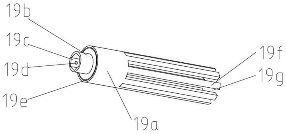
[0029] see figure 1 and figure 2 , figure 1 It is a schematic diagram of a cloth winder for textile use of the present invention, figure 2 A schematic diagram of the winding device. As shown in the figure, the fabric winder for weaving includes a base 1, a first cylinder 3, a flattening device, a tensioning device and a winding device; The tightening device and the winding device provide fixed support for installation; the first roller 3, the flattening device, the tensioning device and the winding device a...


PUM


Abstract

The invention discloses a cloth winding device for spinning. The cloth winding device for spinning comprises a base, a first roller support, a first roller, a lower roller support, an upper roller support, an upper roller, a lower roller, a second roller and a winding drum, wherein the lower roller and the upper roller are oppositely installed, the height of the lower roller can be adjusted through jackscrews, therefore it is guaranteed that a gap between the upper roller and the lower roller meets the requirements of cloth, the height of a moving table is adjusted through an adjusting stud, the initial tensioning force of the cloth is determined, the second roller can float up and down under the action of a spring, it is guaranteed that certain tensioning force always exists in the clothwinding process, the winding drum is formed by splicing and inserting two half drum bodies, the width of the winding drum is adjustable, and the requirements of cloth of different specifications are met. When winding is started, the cloth is fixed to the winding drum through a U-shaped spring clamp, the cloth sequentially passes through the first roller, the upper roller, the lower roller and thesecond roller and is finally wound around the winding drum, and the cloth is wound and fixed to the winding drum through the U-shaped spring clamp.

Description

technical field [0001] The invention relates to the technical field of textiles, in particular to a cloth winder for textiles. Background technique [0002] In the textile factory, textile workers need to wind the textiles onto the rolling tool. After the rolling is completed, the textile worker will remove the rolled cloth. However, the existing rolling tools are very difficult to install and fix. Convenient; the width of the cloth produced is not fixed. For cloth of different widths, the existing technology can only use different winding equipment, which requires multiple winding devices, which is costly and requires equipment replacement. Time-consuming and labor-intensive, resulting in low production efficiency; if the tension of the textile material is insufficient when rolling the material, it will often appear folded and wrinkled; and the textile workers need to manually bind the cloth strips to the winding tool before winding, which wastes Time and work efficiency a...

Claims


Application Information

Patent Timeline
Patent Type & Authority Applications(China)
IPC IPC(8): B65H75/10B65H75/18B65H75/24B65H75/28B65H23/34B65H23/26B65H23/16B65H20/02B65H19/30B65H18/14
CPCB65H75/10B65H75/241B65H75/285B65H75/18B65H19/30B65H18/145B65H20/02B65H23/16B65H23/26B65H23/34B65H2701/174
Inventor 刘虎城张尧宗
Owner SANYANG TEXTILE
Learn More