


Quick Research
Generate reliable direction feasibility study reports for your R&D in just a few steps.

Technical Q&A
Discover and master advanced knowledge NOW. Basics, ideas, possibilities, all at once.

Find Solutions
As an expert in R&D theories, this can generate solutions to your technical problems instantly.

Evaluate Feasibility
Analyze your overall solution with one click, know your potential R&D risks in advance.

Monitor Landscape
Get weekly tech updates, stay abreast of the latest tech innovations and key insights.
Cleaning assembly
A cleaning component and cleaning technology, applied to cleaning methods and tools, cleaning methods using tools, electrical components, etc., can solve the problems of low cleaning efficiency of manual cleaning components, reduce the frequency of moving back and forth, be easy to carry, and easy to use Effect
- Summary
- Abstract
- Description
- Claims
- Application Information
AI Technical Summary
Problems solved by technology
Method used
Image


Examples
Embodiment 1
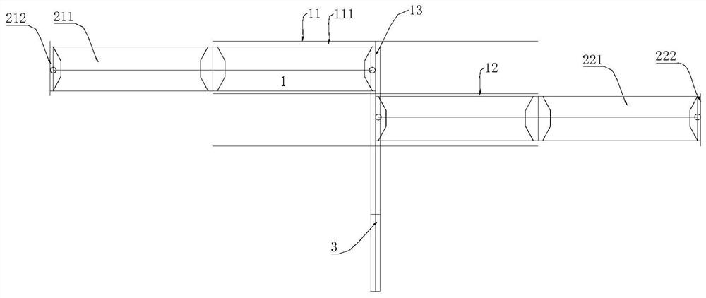
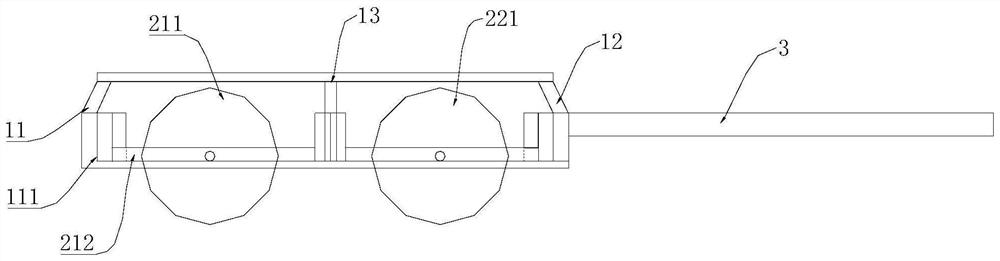
[0045] see Figure 1-Figure 3 As shown, this embodiment provides a cleaning assembly, including a frame body 1 and a cleaning part 2 located thereon, wherein: the cleaning part 2 is used to clean the workpiece to be treated when the frame body 1 moves, and the extension length of the cleaning part 2 Adjustable setting, and adjusting the extension length of the cleaning part 2 can adjust the coverage area swept by the cleaning part 2 on the surface of the workpiece to be treated when cleaning the workpiece in a predetermined direction.
[0046] Wherein, the extension length of the cleaning part 2 can be adjusted in any direction, and the above-mentioned "predetermined direction" refers to a direction that is not parallel to the length adjustment direction of the cleaning part 2, such as figure 1 and figure 2 As shown, the extension length of the cleaning part 2 in this embodiment can be adjusted in the left and right directions in the figure, and the user can move the frame b...
Embodiment 2
[0069] When the first supporting frame 212 in this embodiment moves between the fully retracted state and the fully expanded state, it needs to be able to stay at any position on the first frame body 11 so as to fix the extension length of the cleaning part 2 .
[0070] In order to achieve the above purpose, as an optional implementation, such as Figure 5 As shown, there is a limit mechanism between the support frame and the frame body 1, and the limit mechanism is used to fasten the two when the support frame slides on the frame body 1 to a target position.
[0071] Specifically, such as Figure 5 The limiting mechanism in this embodiment can be a plurality of holes 112 arranged at intervals on the extension length of the first frame body 11, and a bolt (or pin body, etc.) can pass through one of the holes 112 to abut against the first frame body 11. The side wall of the support frame 212 (or through the first support frame 212) realizes the fastening of the two, and the fi...
Embodiment 3
[0073] There may be relatively stubborn dirt on the surface of the parts to be treated such as photovoltaic modules. At this time, the method of rolling the cylinder on the surface may not be able to clean the dirt well.
[0074] In order to improve the cleaning effect of the cleaning assembly, as an optional implementation, in this embodiment, there is a locking mechanism between the support frame and the connecting shaft 213, and the locking mechanism is used to limit the rolling of the cylinder.
[0075] When the locking mechanism restricts the rolling of the cylinder, it can provide greater friction to clean the dirt on the surface of the photovoltaic module, which is suitable for dirt that is difficult to clean.
[0076] Specifically, see Figure 6 and Figure 7 as shown, Figure 7 The direction of the middle arrow indicates a rotation direction of the connecting shaft. When the frame is manually moved, the cylinder sweeps the surface of the workpiece to be processed, a...
PUM
 Abstract
Description
Claims
Application Information
 - R&D Engineer
- R&D Manager
- IP Professional
- Industry Leading Data Capabilities
- Powerful AI technology
- Patent DNA Extraction
Browse by: Latest US Patents, China's latest patents, Technical Efficacy Thesaurus, Application Domain, Technology Topic, Popular Technical Reports.
© 2024 PatSnap. All rights reserved.Legal|Privacy policy|Modern Slavery Act Transparency Statement|Sitemap|About US| Contact US: help@patsnap.com