Glass window for lidar application

A glass window and glass technology, applied in glass/slag layered products, windows/doors, using re-radiation, etc., can solve problems such as signal fluctuations

Pending Publication Date: 2021-01-29
SCHOTT AG
View PDF2 Cites 2 Cited by
  • Summary
  • Abstract
  • Description
  • Claims
  • Application Information

AI Technical Summary

Problems solved by technology

However, none of the glazing described in the prior art, or other glazing known in practice, is really suitable for use in LiDAR systems, because until now, when using existing glazing, high signal fluctuations

Method used


Image

  • Glass window for lidar application
  • Glass window for lidar application
  • Glass window for lidar application

Examples


Embodiment Construction

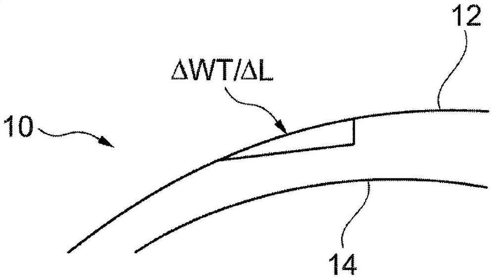
[0213] figure 1 A schematic cross-section of a glazing 10 is shown, which is only used to illustrate the geometric slope error ΔWT / ΔL. So, to get a better overview, figure 1 Only the outer side change of the contour is shown. However, it should be understood that, in the sense of the invention, for slope errors, wall thickness variations are relevant, which are caused jointly by errors and / or contour variations of the outer and inner contours.

[0214] The glazing 10 has a convex curvature outwardly. A first surface 12 on the outside of the glazing 10 and a second surface 14 on the inside of the glazing 10 can be seen. Along the length (in this case the circumference), the glazing 10 has fluctuations or variations in wall thickness. By varying the length of a certain length range (ΔL) or here the wall thickness (WT) over a portion of the circumference, there is a local slope deviation from the ideal curvature target value in this portion of the glazing.

[0215] The inv...


PUM

PropertyMeasurementUnit
thicknessaaaaaaaaaa
lengthaaaaaaaaaa
angleaaaaaaaaaa

Abstract

The disclosure relates to a glass window for optical systems, in particular for LiDAR systems, in which the glass window has a curved form. For length scales between 0.1 mm and 15 mm, at least 50% ofthe area of the glass window has a geometrical slope error SEG for which the following is true: SEG<-2.3*10<-6>*2*R0[1 / mm]+7.3*10<-4>.

Description

technical field [0001] The invention relates to a glazing for optical systems and instruments, in particular for LiDAR systems (LiDAR: Light Detection and Ranging). Furthermore, the invention relates to a LiDAR system with such a glazing as well as a method for producing such a glazing. Background technique [0002] LiDAR (short for "Light Detection and Ranging") or LaDAR (short for "Laser Detection and Ranging") is a method of optically measuring distance and speed by means of laser light, hereinafter referred to as LIDAR. For this purpose, the LiDAR system emits laser radiation in the near-infrared spectrum (NIR), ie with a wavelength greater than 780 nm, which is reflected from surrounding objects and at least partially reaches the LiDAR system again and is detected. Based on the pattern of reflected radiation, LiDAR systems can identify objects and calculate their distance based on the travel time of the laser radiation. Some LiDAR systems can also calculate the veloci...

Claims


Application Information

Patent Timeline
Patent Type & Authority Applications(China)
IPC IPC(8): E06B9/24E06B3/30E06B7/28
CPCE06B9/24E06B7/28E06B3/30E06B2009/2405G01S17/931G01S7/4813C03C4/10C03C17/00C03C3/091C03C4/02B32B17/10G01S7/4814G01S7/4817G02B1/11G02B5/208
Inventor N·舒尔茨B·艾希恩F-T·雷特斯J·U·托马斯V·普拉珀
Owner SCHOTT AG
Why Eureka
Try Eureka