
High-speed wind tunnel free rock test device

A test device, high-speed wind tunnel technology, applied in the direction of measuring device, aerodynamic test, machine/structural component test, etc., can solve problems that threaten flight safety, difficulties, affect flight control stability, etc., and achieve good economy , the effect of convenient installation

Inactive Publication Date: 2021-01-26
INST OF HIGH SPEED AERODYNAMICS OF CHINA AERODYNAMICS RES & DEV CENT
View PDF8 Cites 4 Cited by
  • Summary
  • Abstract
  • Description
  • Claims
  • Application Information

AI Technical Summary

Problems solved by technology

[0002] Even if the roll angle of the aircraft is zero during the flight, non-command rocking will also occur due to the aerodynamic characteristics of the asymmetric flow separation of the air flow around, asymmetric vortex and vortex rupture. According to the different aerodynamic layout, at some angles of attack Limit cycle vibration, double limit cycle vibration and even roll and divergence will be generated under the condition, which will seriously affect the stability of flight control and threaten flight safety.
[0003] However, the current wind tunnel test adopts fixed support regardless of the tail brace, belly brace (back brace) or wingtip support, which can only obtain the steady-state aerodynamic characteristics and static stability of the aircraft, and cannot reflect the actual flight process of the aircraft. The dynamic aerodynamic problems of the aircraft bring uncertainties and difficulties to the evaluation of the dynamic aerodynamic characteristics of the aircraft

Method used


Image

  • High-speed wind tunnel free rock test device
  • High-speed wind tunnel free rock test device

Examples


Embodiment 1

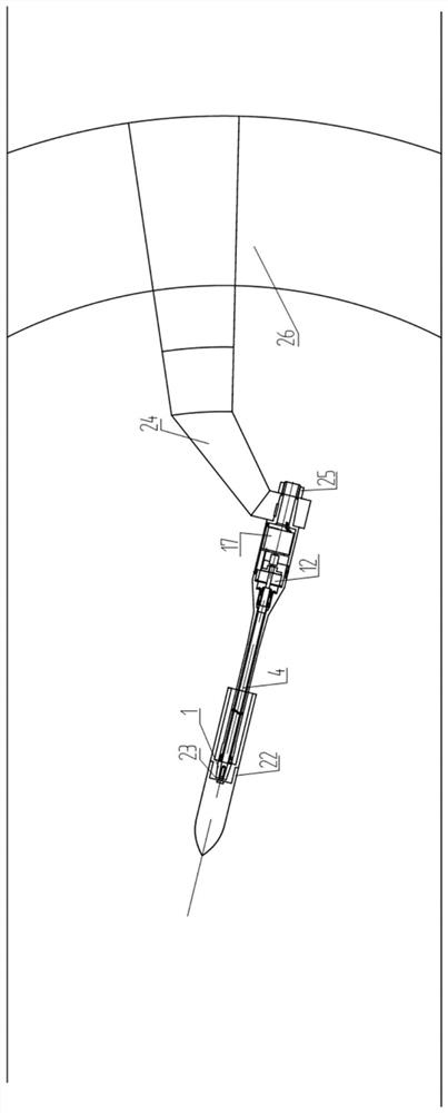
[0035] Such as figure 2 As shown, the high-speed wind tunnel free rock test device of this embodiment is applied in a high-speed wind tunnel.

[0036] In the high-speed wind tunnel free rock test device of this embodiment, when the components are assembled, the mandrel 4 and the front section 5 of the strut are first installed, and the coaxiality of the mandrel 4 and the front section 5 of the strut is checked and adjusted to ensure that the coaxiality is consistent. More than 0.02mm, in order to reduce mechanical friction damping as much as possible; Secondly, install the friction disc with electromagnetic coil of the electromagnetic clutch 12, the mandrel 4 passes through the center hole of the friction disc, and the diameter of the mandrel 4 in this section is smaller than the center hole of the friction disc ; Subsequently, install another friction disc on the mandrel 4, this friction disc can slide along the axial direction of the mandrel 4 for a small distance, utilize ...


PUM


Abstract

The invention discloses a high-speed wind tunnel free rock test device. The test device comprises a supporting rod front section and a supporting rod rear section which share the same central axis, wherein a mandrel is arranged on the central axis of the supporting rod front section; the front end of the mandrel extends out of the front section of the supporting rod, and a copper sleeve fixedly connected with a test model is mounted at the front end; a conical section connected with the crank arm support is arranged at the rear end of the supporting rod rear section; a ball bearing is arrangedat the front section of the mandrel and behind the copper sleeve; an angular contact ball bearing and an electromagnetic clutch are sequentially fixed at the rear section of the mandrel; an angle encoder is fixed on a central shaft of the rear section of the supporting rod; the electromagnetic clutch at the front section of the supporting rod is connected with the angle encoder at the rear section of the supporting rod through a coupling; and the mandrel rolls freely in the front section of the supporting rod through a ball bearing and an angular contact ball bearing. The test device can evaluate the dynamic rocking characteristics of the aircraft at different attack angles during high-speed flight, and guides the appearance optimization design and flight control robustness design of theaircraft.

Description

technical field [0001] The invention belongs to the technical field of high-speed wind tunnel tests, and in particular relates to a high-speed wind tunnel free rock test device. Background technique [0002] Even if the roll angle of the aircraft is zero during the flight, non-command rocking will also occur due to the aerodynamic characteristics of the asymmetric flow separation of the air flow around, asymmetric vortex and vortex rupture. According to the different aerodynamic layout, at some angles of attack Limit cycle vibration, dual limit cycle vibration, and even roll-over divergence will occur under these conditions, seriously affecting the stability of flight control and threatening flight safety. [0003] However, the current wind tunnel test adopts fixed support regardless of the tail brace, belly brace (back brace) or wingtip support, which can only obtain the steady-state aerodynamic characteristics and static stability of the aircraft, and cannot reflect the ac...

Claims


Application Information

Patent Timeline
Patent Type & Authority Applications(China)
IPC IPC(8): G01M9/04G01M9/06
CPCG01M9/04G01M9/062
Inventor 马上赵忠良李玉平杨海泳陶洋李浩王晓冰邓吉龙李乾陈建中
Owner INST OF HIGH SPEED AERODYNAMICS OF CHINA AERODYNAMICS RES & DEV CENT
Learn More