A new energy vehicle charging pile

A technology for new energy vehicles and charging piles, applied in electric vehicle charging technology, charging stations, electric vehicles, etc., can solve the problem that the charging pile does not have vehicle detection and identification functions, does not have a buffer protection effect, and the installation of the charging pile is not convenient and fast. and other problems, to achieve the effect of improving the safety of use, simple and convenient operation, and easy installation

Active Publication Date: 2021-10-26
HEFEI UNIV
View PDF6 Cites 0 Cited by
  • Summary
  • Abstract
  • Description
  • Claims
  • Application Information

AI Technical Summary

Problems solved by technology

[0003] At this stage, the installation of charging piles is not convenient and fast enough, and the existing charging piles do not have vehicle detection and identification functions, and do not have the buffer protection effect when being hit

Method used


Image

  • A new energy vehicle charging pile
  • A new energy vehicle charging pile
  • A new energy vehicle charging pile

Examples


Embodiment 1

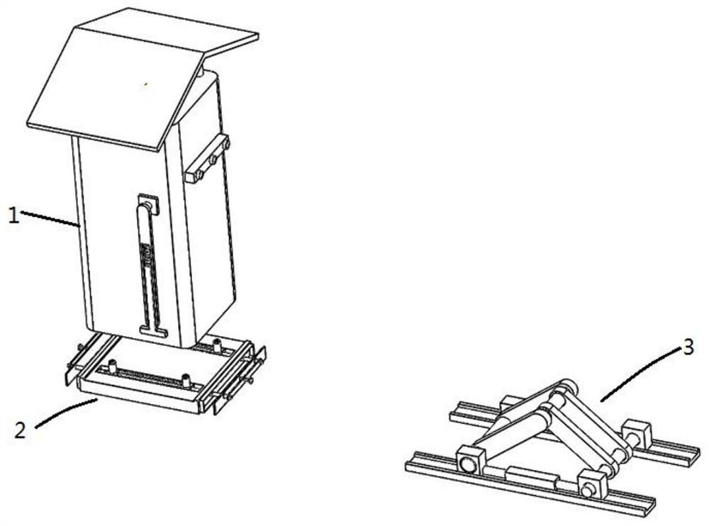
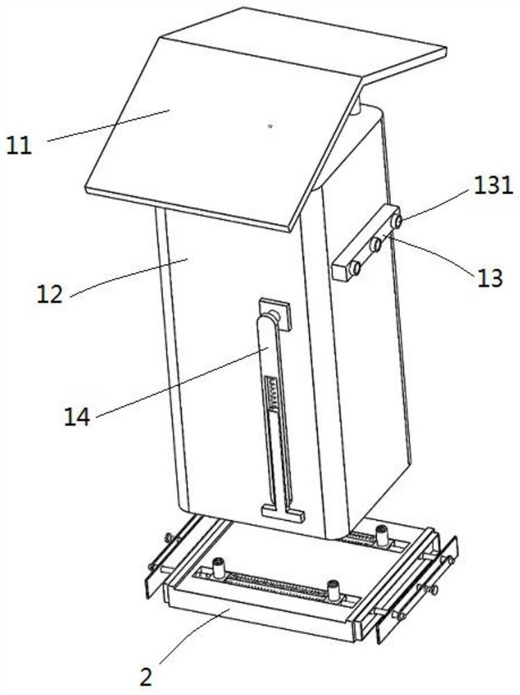
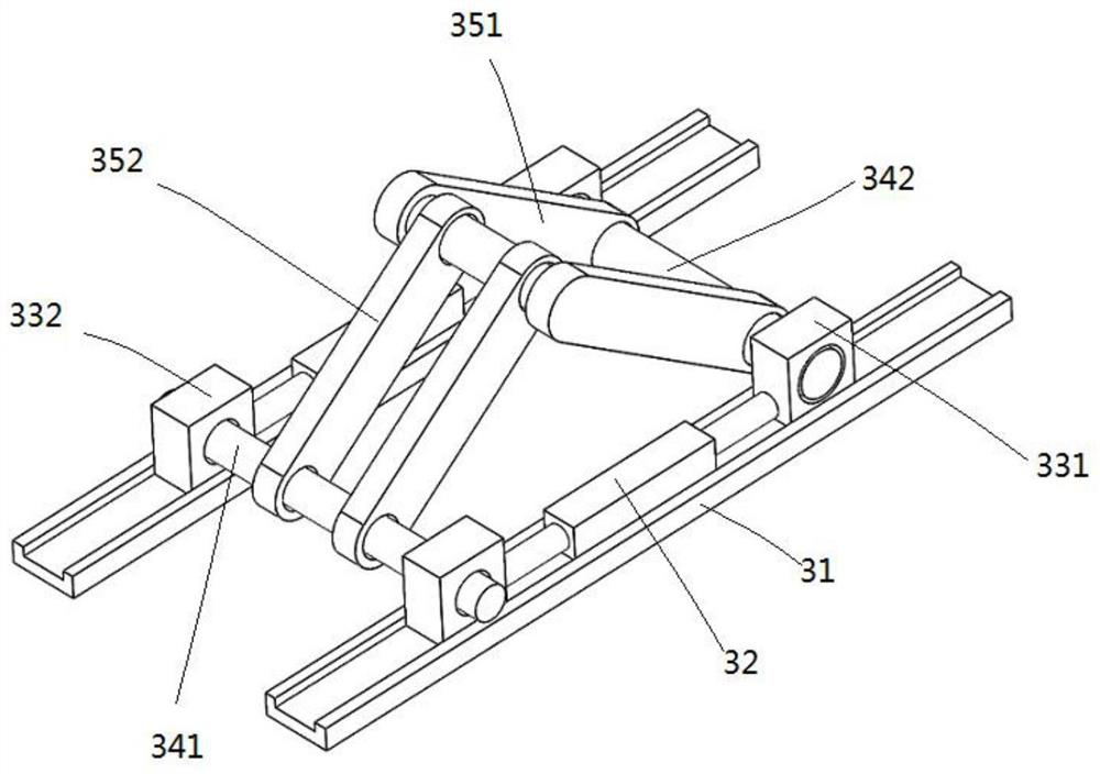
[0036] see Figure 1-8 , a charging pile for new energy vehicles, comprising a pile body 1 detachably connected to a base 2 at the bottom of the pile body 1, a ground lock assembly 3 and a controller, and the ground lock mechanism 3 is installed on the ground near the pile body 1.

[0037] The opposite sides of the pile body 1 are provided with rotatable protection mechanisms 14, the front side of the pile body 1 is equipped with detection components, and the bottom surface of the pile body 1 is provided with several positioning holes.

[0038] The base 2 includes a base plate 21 and two guide rods 29, two parallel grooves 22 are symmetrically arranged on the top surface of the base plate 21, and the two guide rods 29 are respectively fixed in the two grooves 22, and the guide rods Both ends of 29 respectively pass through the base plate 21 and are fixed with locking pieces 291 .

[0039] Each groove 22 is provided with two movable blocks 23 that are slidingly socketed with t...

Embodiment 2

[0052] see Figure 5 as well as Figure 7 , this embodiment is a further improvement on the basis of Embodiment 1, an installation chamber 15 is set up on one side of the pile body 1, and a cable 41 is wound in the installation chamber 15, and a charging gun 42 is installed at the end of the cable 41 , The side of the pile body 1 is also provided with a plug-in block 17 plugged with the tip of the charging gun 42 , and a positioning mechanism is provided on the outside of the plug-in block 17 for fixing the charging gun 42 .

[0053] Further, the positioning mechanism includes a bump 51, a connecting spring 52, and a positioning pin 53, the bump 51 is fixed on the outside of the plug block 17, one end of the positioning pin 53 is connected to the bump 51 through a pin shaft, and the positioning pin 53 and the outer side of the plug block 17 are connected by a connecting spring 52 , and a pin groove corresponding to the positioning pin 53 is opened on the shell of the charging...


PUM


Abstract

The invention relates to the technical field of charging piles, and discloses a charging pile for new energy vehicles, which includes a base that is detachably connected to the bottom of the pile body, a ground lock assembly and a controller, and the ground lock mechanism is installed on the ground near the pile body Above, the opposite sides of the pile body are equipped with rotatable protection mechanisms, the front side of the pile body is installed with detection components, the bottom surface of the pile body is provided with several positioning holes, the base includes a base plate and two guide rods, the Two parallel grooves are arranged symmetrically on the top surface of the base plate, and two guide rods are respectively fixed in the two grooves, and the two ends of the guide rods respectively pass through the base plate and are fixed with locking pieces. Two movable blocks slidingly socketed with the corresponding guide rods are arranged, and the top surface of the movable blocks is fixed with a positioning column, and the positioning column is used for mating and plugging with the positioning hole on the bottom surface of the pile body. The invention is convenient for installation and disassembly, has the function of anti-collision protection, and can detect and identify vehicle information.

Description

technical field [0001] The invention relates to the technical field of charging piles, in particular to a charging pile for new energy vehicles. Background technique [0002] At present, new energy vehicles refer to the use of unconventional vehicle fuels as power sources. The most common ones are electric vehicles, which need to be charged by charging piles. The function of charging piles is similar to that of fuel dispensers in gas stations, which can be fixed on the ground or walls. , Installed in public buildings (public buildings, shopping malls, public parking lots, etc.) and residential parking lots or charging stations, it can charge various types of electric vehicles according to different voltage levels. The input end of the charging pile is directly connected to the AC grid, and the output end is equipped with a charging plug for charging the electric vehicle. Charging piles generally provide two charging methods: conventional charging and fast charging. People c...

Claims


Application Information

Patent Timeline
Patent Type & Authority Patents(China)
IPC IPC(8): B60L53/31B60L53/35
CPCB60L53/31B60L53/35Y02T10/70Y02T10/7072Y02T90/12
Inventor 宋媛宋建军倘余乐殷辉
Owner HEFEI UNIV
Why Eureka
Try Eureka