
A manual disconnecting and connecting device

A disconnection and integration technology, which is applied in the field of manual disconnection and connection devices, can solve problems such as failure to realize remote control and data Internet transmission, strong dependence on manual operation, and potential safety hazards.

Active Publication Date: 2021-07-06
GUANGDONG POWER GRID CO LTD +1
View PDF0 Cites 0 Cited by
  • Summary
  • Abstract
  • Description
  • Claims
  • Application Information

AI Technical Summary

Problems solved by technology

However, devices such as isolation knife switches that operate without load and can form an obvious isolation point after disconnection have not yet achieved remote control and data online transmission.
When the line is in cold standby and maintenance state, it is necessary to form a visible and obvious disconnection isolation point for the power outage line. At present, the isolation knife switch, floor knife and other equipment of the power supply line need to be manually operated on site with an insulating operating rod. The operation process Relatively primitive and highly dependent on manual operation, there are certain potential safety hazards. At the same time, one operation task involves the closing and closing of multiple isolation switches. Manual operation not only affects the timely power transmission of the line, but also reduces the construction quality of the project.

Method used


Image

  • A manual disconnecting and connecting device
  • A manual disconnecting and connecting device
  • A manual disconnecting and connecting device

Examples


Embodiment 1

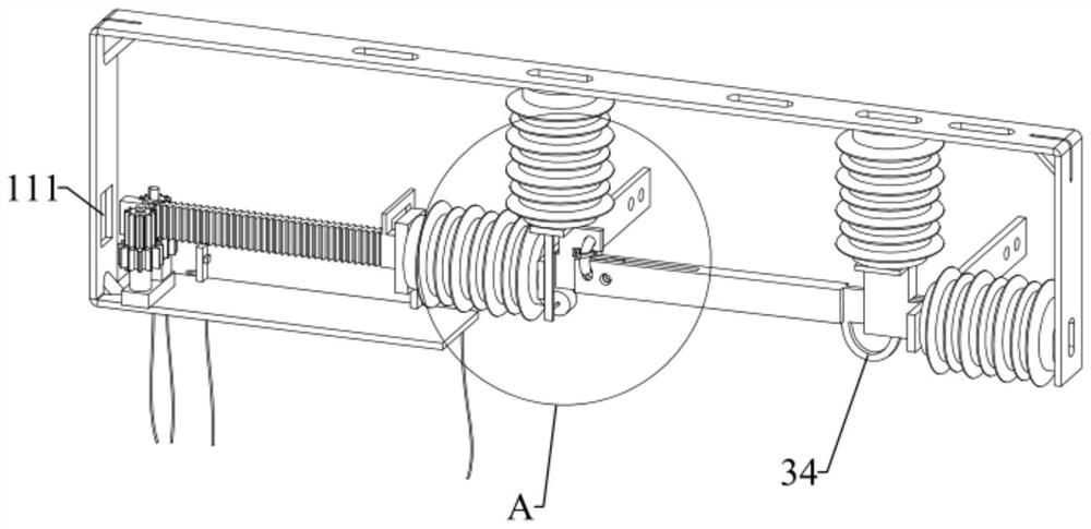
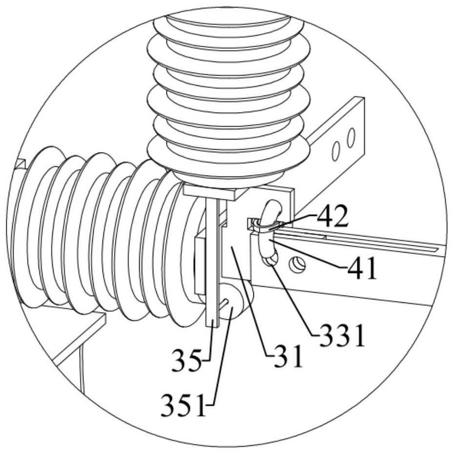
[0033] Such as Figure 1-Figure 3 As shown, the present invention provides a manual disconnecting and connecting device, including a bracket 1, a driving mechanism 2, an opening and closing mechanism 3 and a switching mechanism 4. The bracket 1 includes two vertical frames 11 and a horizontal frame 12, and the two vertical frames The frame 11 is installed on both ends of the horizontal frame 12; the driving mechanism 2 is fixedly installed on one of the vertical frames 11; the opening and closing mechanism 3 includes a first terminal 31, a second terminal 32 and a knife 33, the first terminal 31 Installed on the driving mechanism 2, the second terminal 32 is fixedly installed on the other vertical frame 11, the switch blade 33 is provided with a switching hole 331, one end of the switch blade 33 is rotatably connected to the first terminal 31, and the other end is engaged in the second terminal 32; when the switching mechanism 4 is engaged in the switching hole 331, one end of...

Embodiment 2

[0044] This embodiment provides a manual disconnecting and connecting device, which is further improved on the basis of Embodiment 1. The driving mechanism 2 also includes two sensors 26 and an induction frame 27. The movement of the two sensors 26 along the rack 23 The directions are set on the supporting frame 21 at intervals, and the induction frame 27 is fixedly installed on the rack 23. When the rack 23 drives the induction frame 27 to move, the induction frame 27 can trigger the sensor 26, so that the operator can know the opening and closing of the switch knife 3 state, when the induction frame 27 triggers the sensor 26 near the second terminal 32 side, the sensor 26 sends a signal to the control device, and the control device controls the indicating device (such as an indicator light) to indicate that the switch knife 3 is in a closed state, and the induction frame 27 triggers When away from the sensor 26 on the side of the second terminal 32, the sensor 26 sends a sign...


PUM


Abstract

The invention belongs to the technical field of high-voltage electrical appliances, and discloses a manual disconnecting and connecting device, including a bracket, a driving mechanism, an opening and closing mechanism and a switching mechanism. The bracket includes two vertical frames and a horizontal frame, and the driving mechanism is fixed on a vertical frame. On the frame, the opening and closing mechanism includes a first terminal, a second terminal and a switch blade. The first terminal is installed on the driving mechanism, the second terminal is fixed on another vertical frame, and the switch knife is provided with a switching hole. , one end of the knife is rotatably connected to the first terminal, and the other end is engaged in the second terminal. When the switching mechanism is engaged in the switching hole, one end of the knife is relatively fixed to the first terminal, and the driving mechanism drives the gate The knife comes out from the second terminal, and when the switching mechanism is out of the switching hole, one end of the switch knife can rotate around the first terminal, and the other end of the switch knife can come out from the second terminal. The device can realize the opening and closing of the switch knife in two ways, which improves the speed of line maintenance and ensures the reliability and safety of power supply.

Description

technical field [0001] The invention relates to the technical field of high-voltage electrical appliances, in particular to a manual disconnecting and connecting device. Background technique [0002] At present, electric power equipment is usually required to be able to be remotely controlled by electric power, to realize data online transmission, and to feed back signals in real time. However, devices such as isolation knife switches that operate without load and can form an obvious isolation point after disconnection have not yet achieved remote control and data online transmission. When the line is in cold standby and maintenance state, it is necessary to form a visible and obvious disconnection isolation point for the power outage line. At present, the isolation knife switch, floor knife and other equipment of the power supply line need to be manually operated on site with an insulating operating rod. The operation process Relatively primitive and highly dependent on ma...

Claims


Application Information

Patent Timeline
Patent Type & Authority Patents(China)
IPC IPC(8): H01H31/02
CPCH01H31/02H01H31/026
Inventor 谢升王明怀刘海清陈庆倪博
Owner GUANGDONG POWER GRID CO LTD
Learn More