
Monitoring instrument for realizing automatic adjustment of monitoring position by utilizing photoresistor

A technology of monitoring instruments and photoresistors, which is applied to the control of use feedback, the cleaning method of using tools, instruments, etc., can solve the problems of affecting the monitoring effect and reducing the service life of the instrument screen, so as to improve the effect, prolong the service life, The effect of improving sharpness

Inactive Publication Date: 2021-01-08
广州金彩网络科技有限公司
View PDF8 Cites 2 Cited by
  • Summary
  • Abstract
  • Description
  • Claims
  • Application Information

AI Technical Summary

Problems solved by technology

[0003] When the commonly used security monitoring is in use, since the detection range is fixed during monitoring, in order to monitor all the conditions in the room, multiple monitoring instruments are required to monitor at the same time, and at the same time criminals use the blind spots of the monitoring instruments in dark places. Theft, and the monitoring instrument is placed in a high place after installation and works for a long time, the dust on the instrument screen will seriously affect the monitoring effect, and will reduce the service life of the instrument screen. In order to solve the above problems, the inventor proposed In order to solve the above problems, the inventor proposed a monitoring instrument that uses a photoresistor to automatically adjust the monitoring position

Method used


Image

  • Monitoring instrument for realizing automatic adjustment of monitoring position by utilizing photoresistor
  • Monitoring instrument for realizing automatic adjustment of monitoring position by utilizing photoresistor
  • Monitoring instrument for realizing automatic adjustment of monitoring position by utilizing photoresistor

Examples


Embodiment Construction

[0020]The technical solutions in the embodiments of the present invention will be clearly and completely described below in conjunction with the accompanying drawings in the embodiments of the present invention. Obviously, the described embodiments are only a part of the embodiments of the present invention, rather than all the embodiments. Based on the embodiments of the present invention, all other embodiments obtained by those of ordinary skill in the art without creative work shall fall within the protection scope of the present invention.

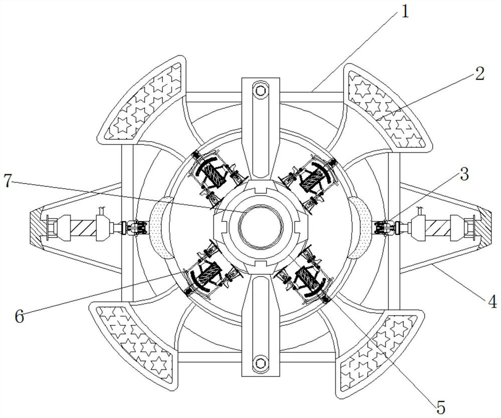
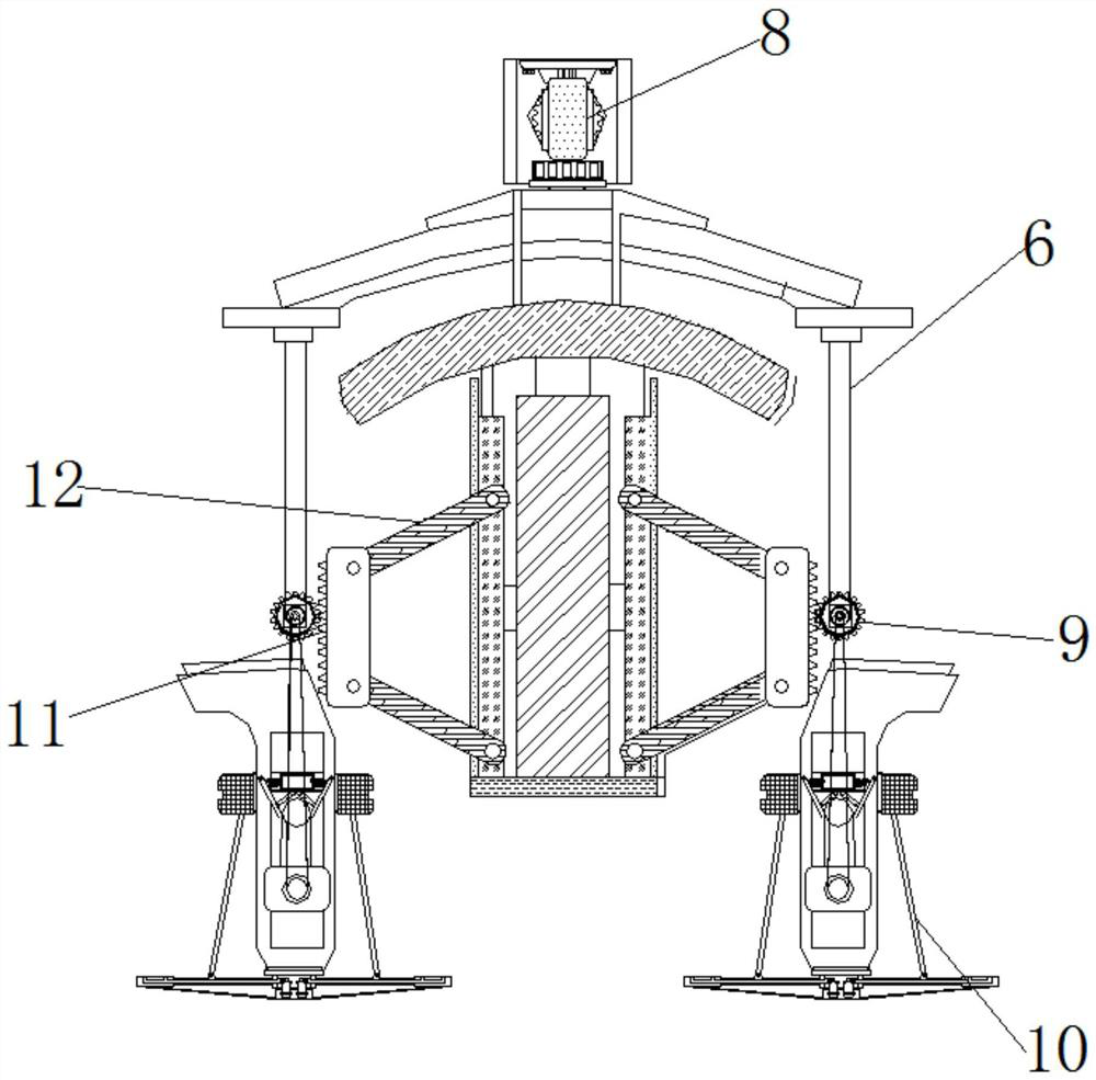
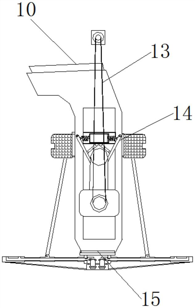
[0021]SeeFigure 1-5, A monitoring instrument that uses a photoresistor to automatically adjust the monitoring position, including a monitoring instrument 1. The outer surface of the monitoring instrument 1 is fixedly connected with a light collecting mirror 2, and the inner side of the monitoring instrument 1 is movably connected with an adjusting device 6 through the light collecting mirror 2 , The top end of the adjusting device 6 is fixedly ...


PUM


Abstract

The invention relates to the technical field of security and protection monitoring and provides a monitoring instrument for realizing the automatic adjustment of a monitoring position by using a photoresistor. The monitoring instrument comprises a monitoring instrument unit, the outer surface of the monitoring instrument unit is fixedly connected with a light collecting mirror, and the inner sideof the monitoring instrument unit is movably connected with an adjusting device through the light collecting mirror. The inner side of the monitoring instrument unit is fixedly connected to a micro control rubber block through the adjusting device. According to the monitoring instrument capable of automatically adjusting the monitoring position through the photoresistor, when the photoresistor issmall and a line is in an on state, a cleaning device is in the on state, a telescopic movable rod on the inner side of the cleaning device is stretched, a spraying agent device is pressed, an air bagis arranged on the upper side of the spraying agent device, airflow in the spraying agent device drives a connecting rod of a rotating block to rotate, the rotating block rotates along with the connecting rod, and the rotating block intermittently extrudes a load spring, so that a cleaning agent is extruded from a spraying tank and led to a cleaning sponge plate; and a telescopic rod drives the cleaning sponge plate to clean the surface of the monitoring head.

Description

Technical field[0001]The invention relates to the technical field of security monitoring, in particular to a monitoring instrument that uses a photoresistor to automatically adjust the monitoring position.Background technique[0002]The security monitoring system uses optical fiber, coaxial cable or microwave to transmit video signals in its closed loop, and constitutes an independent and complete system from camera to image display and recording, which can effectively prevent the occurrence of theft.[0003]When common security monitoring is in use, because the detection range during monitoring is fixed, in order to monitor all the room conditions, multiple monitoring instruments are required to monitor at the same time, and criminals use the blind spots of the monitoring instruments in dim places. Theft, and the monitoring instrument is installed in a high place and working for a long time, the dust on the instrument screen will seriously affect the monitoring effect and reduce the se...

Claims


Application Information

Patent Timeline
Patent Type & Authority Applications(China)
IPC IPC(8): G08B13/196G05D3/12B08B1/00B08B3/08B08B13/00
CPCG08B13/196G05D3/12B08B3/08B08B13/00B08B1/143B08B1/30
Inventor 吴卫玲
Owner 广州金彩网络科技有限公司
Learn More