


Quick Research
Generate reliable direction feasibility study reports for your R&D in just a few steps.

Technical Q&A
Discover and master advanced knowledge NOW. Basics, ideas, possibilities, all at once.

Find Solutions
As an expert in R&D theories, this can generate solutions to your technical problems instantly.

Evaluate Feasibility
Analyze your overall solution with one click, know your potential R&D risks in advance.

Monitor Landscape
Get weekly tech updates, stay abreast of the latest tech innovations and key insights.
Positionable 3D printed elbow joint brace
A 3D printing and elbow joint technology, applied in the field of elbow joint braces, can solve the problems of inconvenient replacement and adjustment, and achieve the effects of convenient replacement, convenient mutual movement, and convenient use
- Summary
- Abstract
- Description
- Claims
- Application Information
AI Technical Summary
Problems solved by technology
Method used
Image

Examples
Embodiment 1
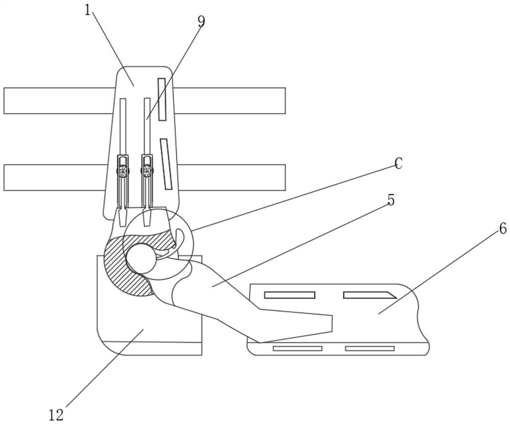
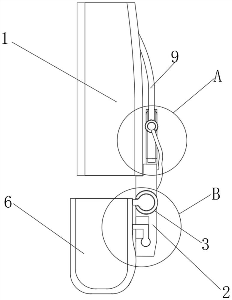
[0022] see Figure 1-3 , a positionable 3D printed elbow brace, comprising an upper arm fixing shell 1, a connecting winch 2 is movably connected to the surface of the upper arm fixing shell 1, and the inside of the connecting winch 2 is provided with a clamping groove 3, and the clamping groove 3 The inner wall is movably connected with a connecting ball 4, the side of the connecting ball 4 is fixedly connected with a connecting frame 5, the surface of the connecting winch 2 is provided with a mounting groove suitable for the connecting frame 5, and the connecting frame 5 is fixedly connected with an end far away from the connecting winch 2. The forearm fixing shell 6, the surface of the forearm fixing shell 6 and the upper arm fixing shell 1 are all equipped with Velcro straps, the top surface of the connecting winch 2 is fixedly connected with a connecting sleeve 7, and the inner wall of the connecting sleeve 7 is movably connected with a fixing ball 8. The surface of the c...
Embodiment 2
[0025] see Figure 4 , the surface of the front of the connecting winch 2 near the top is fixedly connected with an elastic fixed rod 10, the top of the elastic fixed rod 10 is fixedly connected with a stabilizing ball 11, and the bottom surface of the fixed ball 8 is provided with a draw-in groove suitable for the stabilizing ball 11, and the stabilizing ball 11 is clamped with the inwall of the draw-in groove, the surface of the fixed ball 8 is provided with anti-slip protrusions, the inwall of the movable groove on the surface of the connection sleeve 7 is provided with an anti-slip rubber pad, and the elastic fixing rod 10 and the number of the connection sleeve 7 are equal. There are two, and the two elastic fixing rods 10 and the connecting sleeve 7 are horizontally distributed on the top surface of the connecting winch 2 .
[0026] The difference from Embodiment 1 is that through the elastic fixing rod 10 and the stabilizing ball 11, the stabilizing ball 11 can be snapp...
Embodiment 3
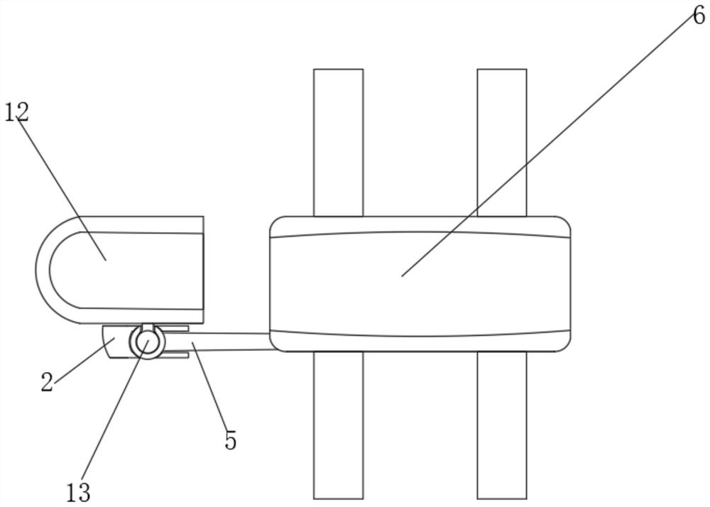
[0028] see Figure 5-6 , the back side of the connection winch 2 is movably connected with an elbow stabilizing shell 12, and the front side of the elbow stabilizing shell 12 is fixedly connected with an installation ball 13, and the back side of the connection ball 4 is provided with a draw-in groove suitable for the installation ball 13, and the elbow is stable. The front of shell 12 is fixedly connected with L-shaped flap 14, and one end of L-shaped flap 14 away from elbow stable shell 12 is provided with spherical block, and the back side of connecting capstan 2 is provided with L-shaped flap 14 and spherical block. Adapted draw-in slot, the inner wall of the draw-in slot that is set on the surface of the connection winch 2 and is compatible with the connecting ball 4 and the connecting frame 5 is fixedly connected with an elastic clamp block 15, and the front shape of the elastic clamp block 15 is T-shaped, and the elastic clamp One end of the block 15 is movably connecte...
PUM
 Abstract
Description
Claims
Application Information
 - R&D Engineer
- R&D Manager
- IP Professional
- Industry Leading Data Capabilities
- Powerful AI technology
- Patent DNA Extraction
Browse by: Latest US Patents, China's latest patents, Technical Efficacy Thesaurus, Application Domain, Technology Topic, Popular Technical Reports.
© 2024 PatSnap. All rights reserved.Legal|Privacy policy|Modern Slavery Act Transparency Statement|Sitemap|About US| Contact US: help@patsnap.com