
Gear shifting mechanism with self-positioning and gear shifting return functions

A shift mechanism, self-positioning technology, applied in the direction of components with teeth, mechanical equipment, belts/chains/gears, etc., can solve the ability to keep the shift lever in the middle position all the time, and affect the service life of the shift mechanism. , The shift lever is prone to problems such as shaking gaps, which can improve the handling experience, the structural design is reliable and reasonable, and the effect of avoiding shifting

Pending Publication Date: 2021-01-05
HEFEI HUAJUN AUTOMOBILE PARTS
View PDF6 Cites 0 Cited by
  • Summary
  • Abstract
  • Description
  • Claims
  • Application Information

AI Technical Summary

Problems solved by technology

[0004] (1) There is only one friction pair in the slider in the existing shifting mechanism, so the friction pair is subjected to a large force and a long time of force during shifting, and is easy to be worn out, so it needs to be replaced regularly, which affects the use of the shifting mechanism life
[0005] (2) The slider in the existing shift mechanism has only one friction pair. When the slider moves to the neutral position, the ability to keep the shift lever in the middle position is poor, so the shift lever is prone to shaking gaps
[0006] (3) The slider in the existing shifting mechanism has only one friction pair. After a period of use, when the slider moves to the forward gear limit area or the reverse gear limit area, it is prone to astringent feeling, which cannot make the shift feel Softer, reducing the driving experience

Method used


Image

  • Gear shifting mechanism with self-positioning and gear shifting return functions
  • Gear shifting mechanism with self-positioning and gear shifting return functions
  • Gear shifting mechanism with self-positioning and gear shifting return functions

Examples


Embodiment Construction

[0041]Combine belowFigure 1 to Figure 14, To further explain the present invention:

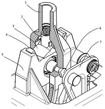
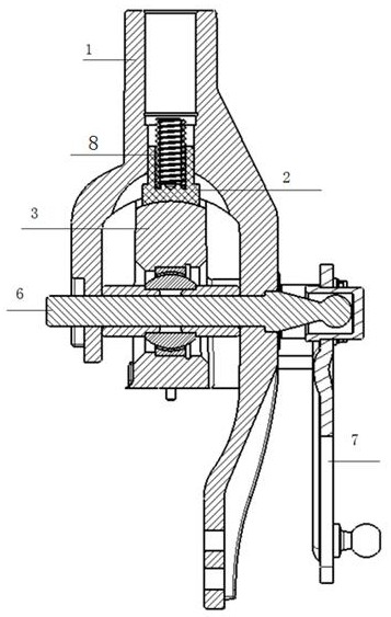
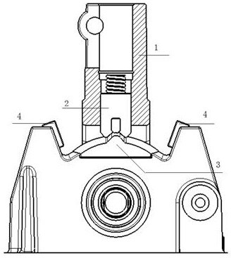
[0042]A shifting mechanism with self-positioning and shifting return, including a shift lever 1 and a mechanism housing 5. The upper end of the shift lever 1 is connected with a control lever, and the lower end of the shift lever 1 is connected with the shift flexible shaft of the automobile. The inner cavity of the shift lever 1 provides the movement space of the slider 2; the slider 2 is located in the inner cavity of the shift lever 1 and can move on the slider seat 3, and the central shaft 6 realizes the shift lever 1, the gear selection rocker 7 The connection with the mechanism housing 5 is characterized in that the slider 2 is provided with a plurality of friction pairs to cooperate with the slider seat 3 to realize the switching of different gear positions, and to avoid the reduction of service life caused by concentrated friction.

[0043]The lower end of the slider 2 is a W-shaped structure. Th...


PUM


Abstract

The invention relates to a gear shifting mechanism with self-positioning and gear shifting return functions. The gear shifting mechanism comprises a gear shifting rod (1) and a mechanism shell (5), the upper end of the gear shifting rod (1) is connected with an operating rod, the lower end of the gear shifting rod (1) is connected with an automobile gear shifting flexible shaft, and an inner cavity of the gear shifting rod (1) provides a movement space for a sliding block (2); and the sliding block (2) is located in the inner cavity of the gear shifting rod (1) and can move on a sliding blockseat (3), and the gear shifting rod (1), a gear selecting rocker arm (7) and the mechanism shell (5) are connected through a center shaft (6). The gear shifting mechanism is characterized in that thesliding block (2) is provided with a plurality of friction pairs matched with the sliding block seat (3) to achieve switching of different gears, and service life shortening caused by concentrated friction is avoided. The gear shifting mechanism is reliable and reasonable in structural design, good in control hand feeling and high in gear shifting suction feeling and positioning feeling, the out-of-gear problem can be effectively avoided, and the control experience of a driver is greatly improved.

Description

Technical field[0001]The invention relates to an automobile gear shifting mechanism, in particular to a gear shifting mechanism with self-positioning and shifting return.Background technique[0002]When selecting gears, the gear shifting rocker arm of the automobile shifts to the left and right, and the gear selection rocker arm rotates around the gear selection rocker arm shaft through the shift shaft. Due to the rotation of the gear selection rocker arm, the gear shift rocker arm will be pulled to produce a deflection. In recent years, there are manual automobile shifting mechanisms at home and abroad that have increased the shift limit structure. This type of manipulator limit structure is integrated with the manipulator seat body, so the deflection of the shift rocker arm causes the limit bolt and the limit Interference or abnormal friction between blocks affects the manipulator[0003]However, the automobile shift mechanism in the prior art still has the following technical defects...

Claims


Application Information

Patent Timeline
Patent Type & Authority Applications(China)
IPC IPC(8): F16H59/02
CPCF16H59/02F16H59/0278F16H2059/0239F16H2059/0256F16H2059/026F16H2059/0295
Inventor 汪亚宾
Owner HEFEI HUAJUN AUTOMOBILE PARTS
Learn More