
Hovercraft based on magnetic levitation

A hovercraft and magnetic levitation technology, applied in the directions of air cushions, foldable/inflatable hulls, hulls, etc., can solve the problems of inconvenient movement and use, large size of the hovercraft, etc., and achieve the effect of ensuring safe use and saving manpower

Inactive Publication Date: 2021-01-05
BENGBU PI ELECTRONIC TECH CO LTD
View PDF0 Cites 0 Cited by
  • Summary
  • Abstract
  • Description
  • Claims
  • Application Information

AI Technical Summary

Problems solved by technology

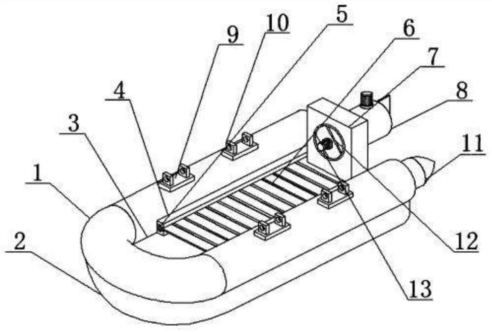
[0003] The hovercraft uses high-pressure air to form an air cushion between the bottom of the ship and the water surface or the ground, so that all or part of the hull can be raised, thereby greatly reducing the resistance of the hull during navigation and realizing high-speed navigation. The hovercraft can also travel at a very slow speed. Hovering, hovercraft are widely used in rescue, sightseeing and other fields due to their high speed and flexibility. Existing hovercraft require workers to change direction and speed when in use. Existing hovercraft are bulky and inconvenient to move and use. , the existing hovercraft cannot change the contact area between the hovercraft and the water surface during use, and cannot rotate and switch according to the use environment and use the resistance of the water. Therefore, a hovercraft with magnetic levitation function is invented to meet the needs of the current situation.

Method used


Image

  • Hovercraft based on magnetic levitation
  • Hovercraft based on magnetic levitation
  • Hovercraft based on magnetic levitation

Examples


Embodiment approach

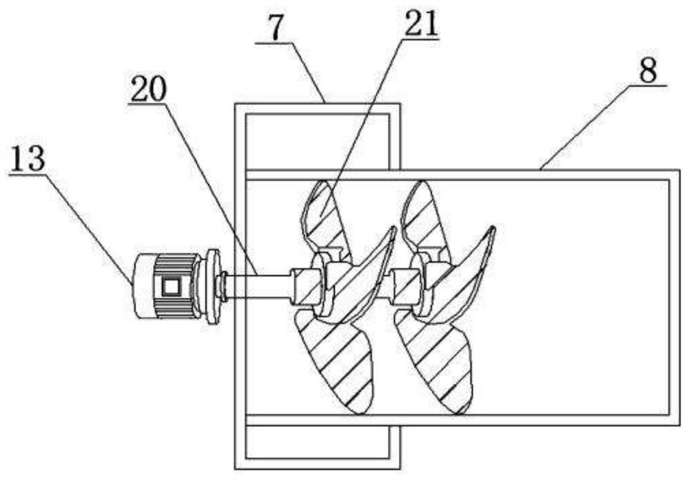
[0029] As a preferred embodiment of the present invention, the control box 31 is electrically connected to the pressure sensor 29 and the air pressure sensor 30 through wires, the control box 31 is electrically connected to the power supply device 34 through wires, and the power supply device 34 is The wires are electrically connected with the first motor 13 , the second motor 14 , the alarm device 35 , the first coil 25 and the second coil 26 .

[0030] As a preferred embodiment of the present invention, the pressure sensor 29 is installed at the bottom of the bottom plate 3 , and the air pressure sensor 30 is installed inside the hull 1 .

[0031] As a preferred embodiment of the present invention, one end of the hull 1 is provided with an inflation joint 11 , and a control valve is disposed on the inflation joint 11 .

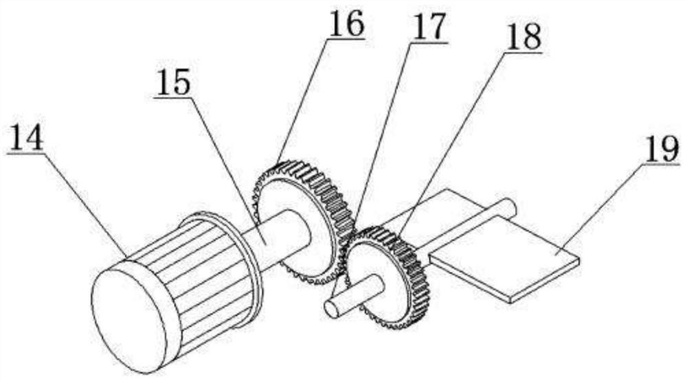
[0032] As a preferred embodiment of the present invention, both ends of the rotating rod 17 are fixed inside the installation barrel 8 through bearings.

...


PUM


Abstract

The invention provides a hovercraft based on magnetic levitation. The hovercraft comprises a hovercraft body, the hovercraft body comprises a ship body and an intelligent system, and the intelligent system comprises a pressure sensor, an air pressure sensor, a control box, an intelligent processor, a control switch, a power supply device, a first motor, a second motor, an alarm device, a first coil and a second coil. An inflatable cushion is arranged at the bottom of the ship body, a first suspension device is arranged between the inflatable cushion and the ship body, a second suspension device and a third suspension device are arranged on the two sides of the first suspension device respectively, a bottom plate is arranged in the ship body, a fixing frame is arranged between the bottom plate and the ship body, a fixing groove is formed in the fixing frame, a fixing plate is arranged in the fixing groove, a box body is arranged at one end of the ship body, a through hole is formed in the box body, and a mounting plate is arranged in the through hole. The hovercraft with the magnetic levitation function has the advantages that the hovercraft is reasonable in design and suitable forpopularization.

Description

[0001] This application is a divisional application of an invention patent application with an application date of August 9, 2019, titled "A Hovercraft with Magnetic Levitation Function", and application number 201910736603.0. technical field [0002] The invention relates to the field of motorboat hovercraft equipment, in particular to a hovercraft based on magnetic suspension. Background technique [0003] The hovercraft uses high-pressure air to form an air cushion between the bottom of the ship and the water surface or the ground, so that all or part of the hull can be raised, thereby greatly reducing the resistance of the hull during navigation and realizing high-speed navigation. The hovercraft can also travel at a very slow speed. Hovering, hovercraft are widely used in rescue, sightseeing and other fields due to their high speed and flexibility. Existing hovercraft require workers to change direction and speed when in use. Existing hovercraft are bulky and inconvenien...

Claims


Application Information

Patent Timeline
Patent Type & Authority Applications(China)
IPC IPC(8): B60V3/06B63B7/08B63H25/20B63B45/00B63B43/02
CPCB60V3/06B63B7/08B63B43/02B63B45/00B63H25/20
Inventor 叶翠容
Owner BENGBU PI ELECTRONIC TECH CO LTD
Learn More