Optical cable connector device convenient to maintain and capable of preventing water accumulation

A fiber optic cable joint and anti-water technology, which is applied in the direction of light guides, optics, optical components, etc., can solve the problems of reduced transmission performance, difficult automatic discharge of accumulated water, and water ingress, so as to reduce workload, facilitate maintenance, and ensure normal transmission Effect

Inactive Publication Date: 2020-12-29
深圳市云陌科技有限公司
View PDF0 Cites 1 Cited by
  • Summary
  • Abstract
  • Description
  • Claims
  • Application Information

AI Technical Summary

Problems solved by technology

[0002] The function of the optical cable splice box is to connect two or more optical cables together and protect the connecting parts of the components. At present, the optical cable splice box installed at a high place will be damaged due to changes in weather temperature and humidity after working for a certain period of time. The sealing performance of the optical cable will decrease, which will lead to water ingress. It is difficult to automatically discharge the accumulated water in the optical cable joint box. Increased the workload of follow-up maintenance. On the other hand, due to the large number of optical cable splice boxes, it is difficult for the staff to judge the location of the faulty splice box when a transmission problem occurs.

Method used


Image

  • Optical cable connector device convenient to maintain and capable of preventing water accumulation
  • Optical cable connector device convenient to maintain and capable of preventing water accumulation
  • Optical cable connector device convenient to maintain and capable of preventing water accumulation

Examples


Embodiment Construction

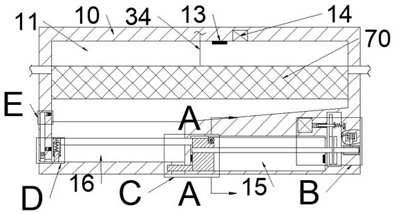
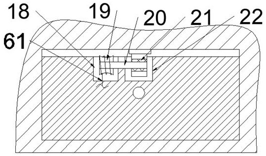
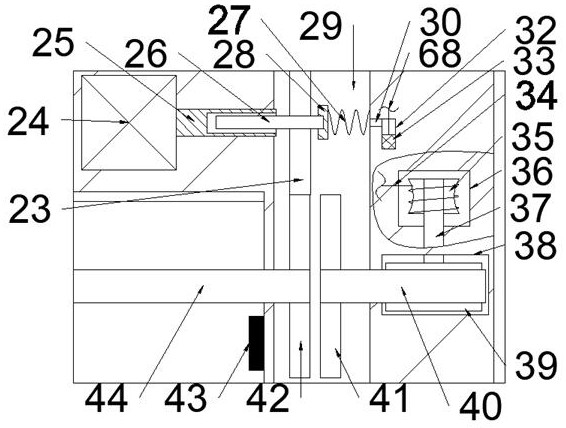
[0017] Combine below Figure 1-6 The present invention is described in detail, wherein, for the convenience of description, the orientations mentioned below are defined as follows: figure 1 The up, down, left, right, front and back directions of the projection relationship itself are the same.

[0018] A maintenance-friendly and anti-water optical cable joint device described in conjunction with accompanying drawings 1-6 includes a main box body 10, and an optical cable cavity 11 is provided inside the main box body 10, and the lower side of the optical cable cavity 11 is communicated with a There is a water accumulation chamber 16, the lower side of the water accumulation chamber 16 is connected with a discharge chamber 47 opening downward, the right side of the water accumulation chamber 16 is provided with a drainage slider chamber 15, and the right side of the drainage slider chamber 15 A clutch cavity 29 is provided, and the left end wall of the clutch cavity 29 is rotat...


PUM


Abstract

The invention relates to the related field of optical cables, and discloses an optical cable connector device convenient to maintain and capable of preventing water accumulation. The optical cable connector device comprises a main box body, an optical cable cavity is formed in the main box body, a water accumulation cavity is formed in the lower side of the optical cable cavity in a communicatingmanner, a discharging cavity with a downward opening is formed in the lower side of the water accumulation cavity in a communicating manner, a drainage sliding block cavity is arranged at the right side of the water accumulation cavity, and a clutch cavity is formed in the right side of the drainage sliding block cavity; a drainage lead screw which extends rightwards into the clutch cavity and extends leftwards into the drainage sliding block cavity is connected into the left end wall of the clutch cavity in a running fit manner, a reverse rotation contact switch is fixedly connected to the right end wall of the drainage sliding block cavity, and a drainage sliding block drives a connecting block and a drainage plate to move rightwards through a drainage connecting rod; in cooperation withsteering changes of a motor, continuous drainage of accumulated water is achieved, an optical cable connector box is kept dry, normal transmission of an optical cable is guaranteed, a protection pullrope drives an optical cable connecting disc to slide upwards, the situation that the optical fiber goes wrong due to the fact that too much accumulated water makes contact with the optical cable isavoided as much as possible, and meanwhile the follow-up maintenance workload is reduced; and the workload is reduced.

Description

technical field [0001] The invention relates to the related field of optical cables, in particular to an optical cable joint device which is convenient for maintenance and prevents accumulation of water. Background technique [0002] The function of the optical cable splice box is to connect two or more optical cables together and protect the connecting parts of the components. At present, the optical cable splice box installed at a high place will be damaged due to changes in weather temperature and humidity after working for a certain period of time. The sealing performance of the optical cable will decrease, which will lead to water ingress. It is difficult to automatically discharge the accumulated water in the optical cable joint box. The workload of follow-up maintenance is increased. On the other hand, due to the large number of optical cable splice boxes, when a transmission problem occurs, it is difficult for the staff to judge the location of the faulty splice box....

Claims


Application Information

Patent Timeline
Patent Type & Authority Applications(China)
IPC IPC(8): G02B6/44
CPCG02B6/4446
Inventor 马付庆
Owner 深圳市云陌科技有限公司
Why Eureka
Try Eureka