A real-time two-way adjustment device based on VR technology
A two-way adjustment device and technology, applied in the field of VR, can solve the problem of observation in other provinces or even abroad, and the observed species or creatures do not have realistic effects, and achieve the effect of convenient popularization and high real-time performance.
- Summary
- Abstract
- Description
- Claims
- Application Information
AI Technical Summary
Problems solved by technology
Method used
Image
Examples
Embodiment 1
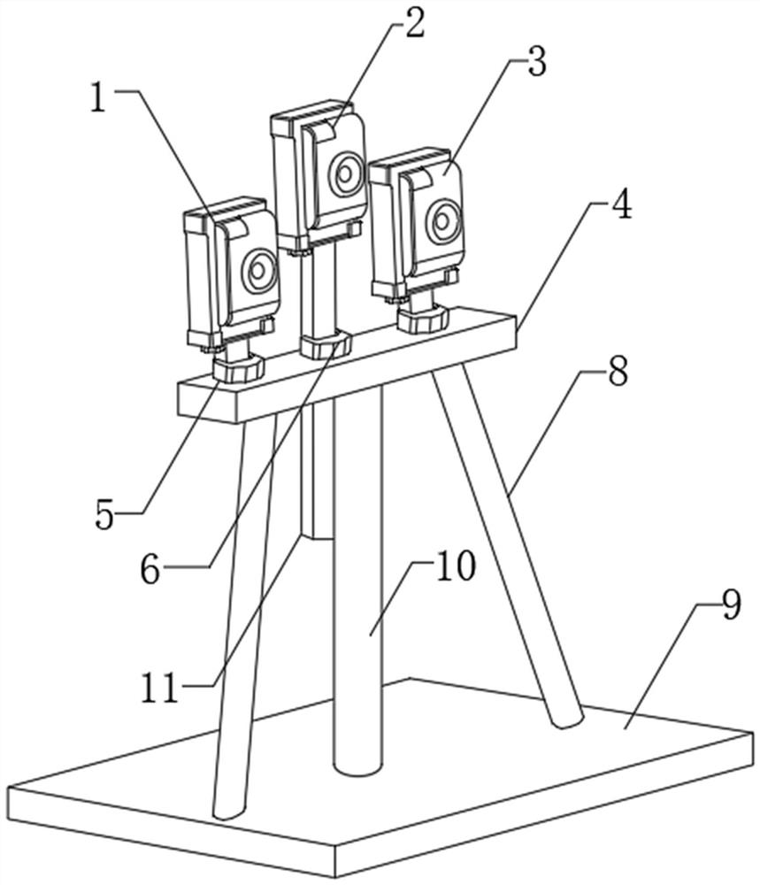
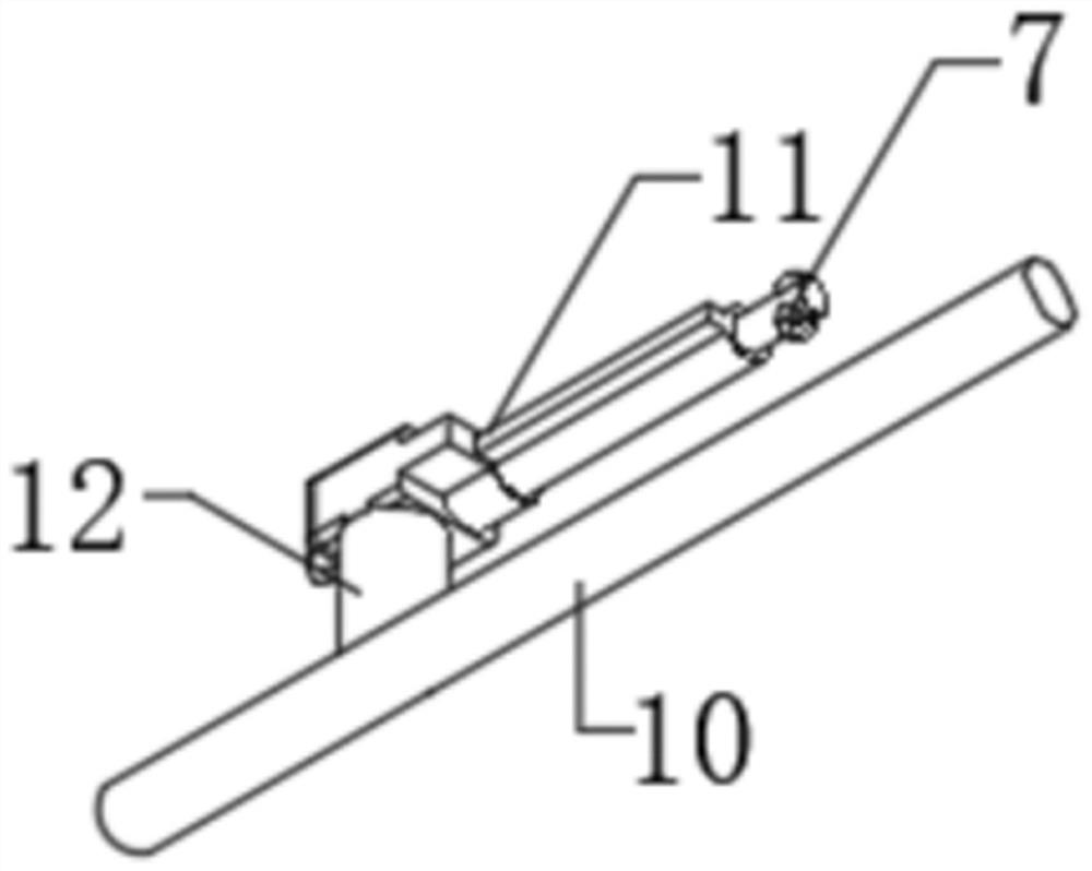
[0025] Such as Figure 1-6 As shown, a real-time two-way adjustment device based on VR technology includes a first camera (1), a second camera (2), a third camera (3) and a mounting plate (4). The internal design of the mounting plate (4) There is an image fitting module, the first fixing buckle (5) is installed on both sides of the top of the mounting plate (4), the second fixing buckle (6) is installed on the middle of the top of the mounting plate (4), and the first fixing buckle (6) is installed on one side. A first camera (1) is installed inside the fixed buckle (5), a connecting rod (7) is installed inside the second fixed buckle (6) in the middle, and a second camera (2) is installed on the top of the connecting rod (7). A third camera (3) is installed inside the first fixing buckle (5) on the other side.
[0026] The middle part of the bottom end of the mounting plate (4) is installed with a support rod (10), and both sides of the bottom end of the mounting plate (4) ...
Embodiment 2
[0033] Such as Figure 1-6 As shown, a real-time two-way adjustment device based on VR technology includes a first camera (1), a second camera (2), a third camera (3) and a mounting plate (4). The internal design of the mounting plate (4) There is an image fitting module, the first fixing buckle (5) is installed on both sides of the top of the mounting plate (4), the second fixing buckle (6) is installed on the middle of the top of the mounting plate (4), and the first fixing buckle (6) is installed on one side. A first camera (1) is installed inside the fixed buckle (5), a connecting rod (7) is installed inside the second fixed buckle (6) in the middle, and a second camera (2) is installed on the top of the connecting rod (7). A third camera (3) is installed inside the first fixing buckle (5) on the other side.
[0034] The inner bottom of the bottom plate (9) is respectively installed with the first storage device (19), the second storage device (20) and the third storage d...
Embodiment 3
[0040] At the same time, in order to facilitate research, we conducted field tests with controllable objects and collected data for comparison, as shown in the following table:
[0041] Table 1:
[0042]
[0043] Table 2:
[0044]
[0045] Note: Table 1 is the observation of static objects, and Table 2 is the observation of dynamic objects. From the combination of Table 1 and Table 2, we can know that when the cameras are arranged dynamically in the triangle shape mentioned above, ignoring the external devices and internal software When the error is small, the measurement accuracy is higher and the imaging effect is the best.
PUM
 Abstract
Description
Claims
Application Information
 - Generate Ideas
- Intellectual Property
- Life Sciences
- Materials
- Tech Scout
- Unparalleled Data Quality
- Higher Quality Content
- 60% Fewer Hallucinations
Browse by: Latest US Patents, China's latest patents, Technical Efficacy Thesaurus, Application Domain, Technology Topic, Popular Technical Reports.
© 2025 PatSnap. All rights reserved.Legal|Privacy policy|Modern Slavery Act Transparency Statement|Sitemap|About US| Contact US: help@patsnap.com


