
Rotor balancing method and apparatus

A technology of rotor balancing and rotor, which is used in measuring devices, static/dynamic balance testing, instruments, etc.

Active Publication Date: 2020-12-22
SIEMWNS ENERGY GLOBAL GMBH & CO KG
View PDF4 Cites 1 Cited by
  • Summary
  • Abstract
  • Description
  • Claims
  • Application Information

AI Technical Summary

Problems solved by technology

In some cases, insensitive rotors required more than 10 runs to balance, resulting in an increase of at least one working day compared to sensitive rotors

Method used


Image

  • Rotor balancing method and apparatus
  • Rotor balancing method and apparatus
  • Rotor balancing method and apparatus

Examples


Embodiment Construction

[0030] The present disclosure relates to methods for balancing rotors used in turbomachines, such as gas turbines.

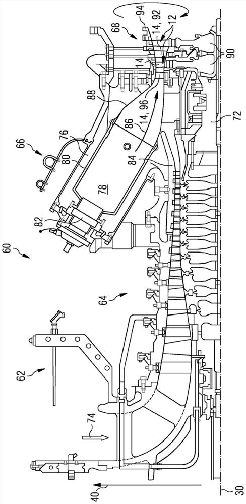
[0031] by context, figure 1 A known arrangement is shown in which the features of the present disclosure may be applied.

[0032] figure 1 One example of a gas turbine engine 60 is shown in a cross-sectional view illustrating the nature of the rotor and the environment in which the rotor operates. Gas turbine engine 60 includes an intake 62 , a compressor section 64 , a combustion section 66 , and a turbine section 68 in a flow order generally arranged in flow order and generally in the direction of the longitudinal or rotational axis 30 . Gas turbine engine 60 also includes a rotor shaft 72 rotatable about axis of rotation 30 and extending longitudinally through gas turbine engine 60 . The axis of rotation 30 is generally the axis of rotation of the associated gas turbine engine. Accordingly, any references to “axial”, “radial” and “circumferential” directi...


PUM


Abstract

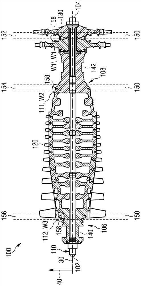
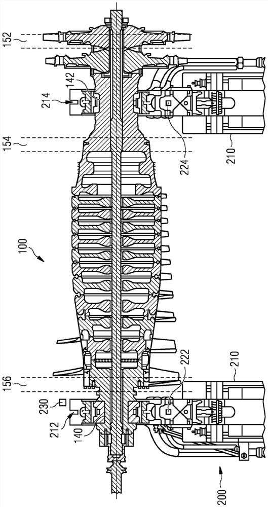
A rotor balancing method for a gas turbine is provided. The method comprises providing a rotor (100) comprising a first correction plane (152) and a second correction plane (154), wherein a first balancing weight (W1) is attached to the first correction plane (152). The method comprises performing a first influence run. The first balancing weight W1 remains fitted for the subsequent second influence run. The method comprises fitting a first calibration weight (M1) to the second correction plane (154) using a reference influence vector. The method comprises performing a second influence run. The method comprises removing the first calibration weight (M1) from the rotor (100) and calculating an influence vector of the second correction plane (154) using a first set of vibration measurementsand a second set of vibration measurements taken during the first influence run and the second influence run, respectively. The method comprises carrying out balancing of the rotor by fitting a finalbalancing weight (W1') to the first correction plane (152) and a second balancing weight (W2) to the second correction plane (154) using the calculated influence vectors.

Description

technical field [0001] The present disclosure relates to gas turbine engines. [0002] In particular, the present disclosure relates to a method of balancing a rotor for a gas turbine engine and an apparatus for balancing the rotor. Background technique [0003] As a specific example of a turbine, a gas turbine engine typically includes a rotor having a plurality of rotating rotor bucket rows fixed to a rotor shaft. As the hot and pressurized working fluid flows through the rows of buckets in the main passage of the gas turbine, the working fluid transfers momentum to the rotor buckets and thereby imparts rotational motion to the rotor. Any imbalance of the rotor will cause vibrations which may adversely affect the efficiency and durability of the gas turbine. Therefore, satisfactory operation requires precise balancing of the rotor to dampen vibrations. To this end, the rotor is subjected to a balancing procedure through which imbalance is assessed and balancing weights ...

Claims


Application Information

Patent Timeline
IPC IPC(8): F01D5/02G01M1/22G01M1/32
CPCG01M1/22G01M1/32F01D5/027F01D5/005F05D2220/32F05D2230/80F05D2240/24
Inventor 孟志强
Owner SIEMWNS ENERGY GLOBAL GMBH & CO KG
Learn More