Connection device, discharge system and method

A technology for connecting equipment and connectors, applied in bridge construction, bridge parts, roads, etc., can solve cumbersome, time-consuming and other problems, and achieve the effect of avoiding cavities, low consumption, and low additional costs

Inactive Publication Date: 2020-12-18
ACO AHLMANN SE & CO KG
View PDF9 Cites 0 Cited by
  • Summary
  • Abstract
  • Description
  • Claims
  • Application Information

AI Technical Summary

Problems solved by technology

[0004] This has the disadvantage that mortar can get into the discharge body when laying the accessories
The method is tedious and time-consuming

Method used


Image

  • Connection device, discharge system and method
  • Connection device, discharge system and method
  • Connection device, discharge system and method

Examples


Embodiment Construction

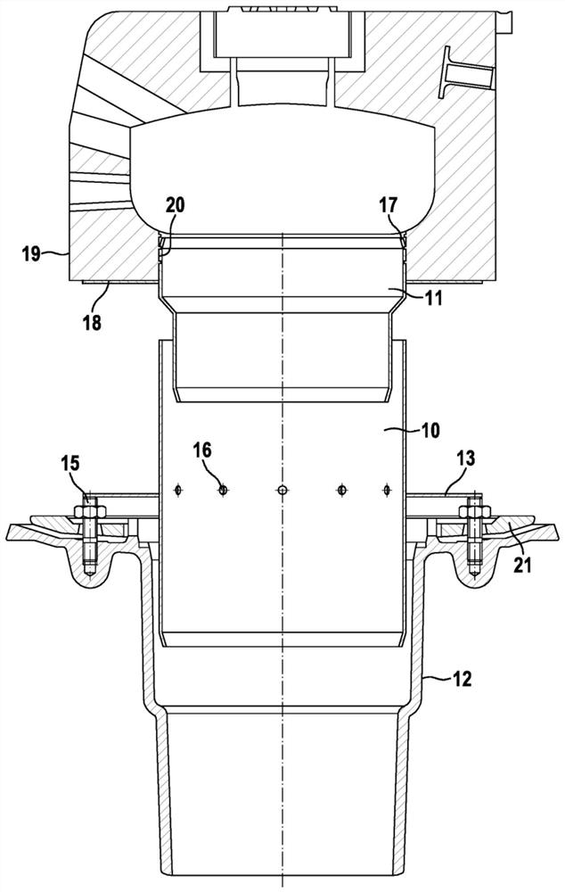
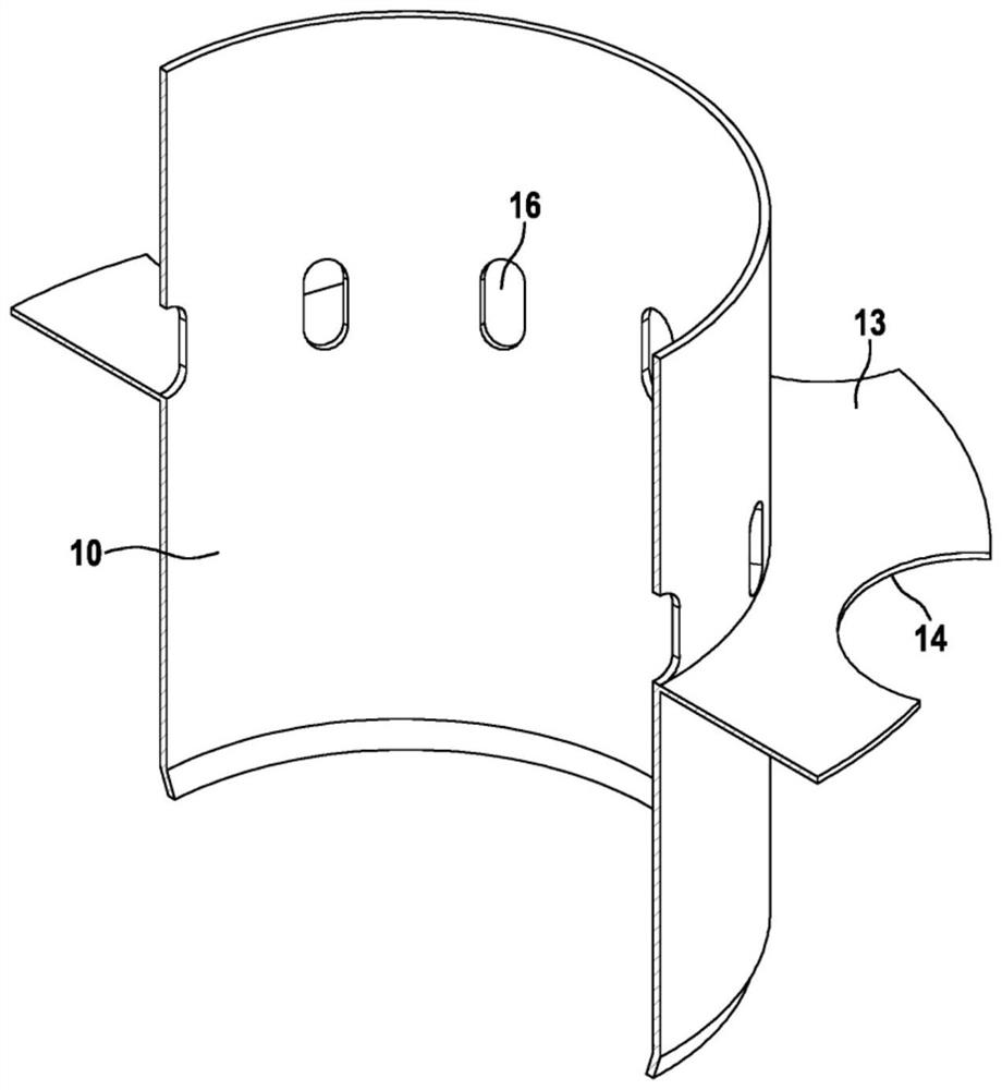
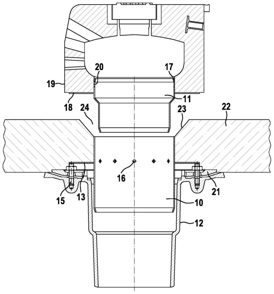
[0029] exist figure 1 shows the connected device with discharge system. The discharge body 12 is fastened in use by means of a compression flange 21 in a solid base, preferably concrete, and connected to the sewage network. The support flange 13 lies flat on the pressure flange 21 of the discharge body 12 . Optionally, the support flange 13 can have a cutout 14 for the screw connection 15 of the outlet body 12 , which cutout enables centering and delimitation of the axial rotation of the boot socket 10 .

[0030] The bearing flange 13 is located between the axial ends of the jacket socket 10 and extends partially into the outlet body 12 . Above the support flange 13 there can be drainage openings 16 on the section of the hood socket 10 that is in direct contact with the mortar, so that the draining Moisture is drawn away from the mortar. Attached to the exposed end of the hood socket 10 is an accessory socket 11 . The accessory socket has a flange 18 extending in the cir...


PUM


Abstract

The invention relates to a connection device for a discharge system for draining traffic surfaces, the connecting device having an attachment pipe, which can be connected to an attachment for drawingoff water, and a discharge member, which can be connected to a sewage system. The invention is characterised in that a casing pipe (10) is arranged between the attachment pipe (11) and the discharge member (12), the casing pipe (10) extending into the discharge member (12) and having a supporting flange (13) which is arranged between the axial ends of the casing pipe.

Description

technical field [0001] The invention relates to a connection device for a drainage system for the drainage of traffic surfaces, wherein the connection device has: an accessory socket, which can be connected to an accessory for discharging water; and a discharge body, which can be connected to Sewage system connection. Background technique [0002] Connecting devices of this type are used in practice, for example, for the drainage of bridges. [0003] In this connecting device, the connection between the attachment and the discharge body consists of a simple tube. The pipe is connected to the attachment by means of a plug connection and is placed together with the attachment on the mortar bed coated around the discharge body. [0004] This has the disadvantage that mortar can get into the discharge body when the attachment is being laid. At the same time, however, sufficient mass must be applied in order to avoid subsequent hollows. Otherwise, the possibility arises that ...

Claims


Application Information

Patent Timeline
IPC IPC(8): E01C11/22E01D19/08
CPCE01C11/223E01C11/224E01D19/086
Inventor 托尔斯滕·克勒姆
Owner ACO AHLMANN SE & CO KG
Why Eureka
Try Eureka