
Driving circuit, driving system, driving method and gearbox

A drive circuit and drive system technology, applied in the fields of gearboxes and drive circuits, can solve problems such as increasing control costs, complex logic application software, and high requirements for performance and computing power.

Inactive Publication Date: 2020-12-18
湖南行必达网联科技有限公司
View PDF2 Cites 1 Cited by
  • Summary
  • Abstract
  • Description
  • Claims
  • Application Information

AI Technical Summary

Problems solved by technology

[0003] However, in the existing technology, a solenoid valve corresponds to a high-end control and a low-end control, which increases the control cost. The high-end controls the power supply and the low-end controls the PWM waveform. When controlling the inductive load of the solenoid valve, it is easy to generate coil energy storage. , especially for PWM-controlled high-speed switching solenoid valves, the requirements for the number of PWM channels, MCU performance and computing power are very high, and the control logic application software also becomes complicated

Method used


Image

  • Driving circuit, driving system, driving method and gearbox
  • Driving circuit, driving system, driving method and gearbox
  • Driving circuit, driving system, driving method and gearbox

Examples


Embodiment Construction

[0031] In order to make the technical solutions and advantages of the embodiments of the present invention clearer, the technical solutions in the embodiments of the present invention will be clearly and completely described below in conjunction with the drawings in the embodiments of the present application. Obviously, the described embodiments are only the present invention. Some, but not all, embodiments are invented. The components of the embodiments of the invention generally described and illustrated in the figures herein may be arranged and designed in a variety of different configurations. Accordingly, the following detailed description of the embodiments of the invention provided in the accompanying drawings is not intended to limit the scope of the claimed invention, but merely represents selected embodiments of the invention. Based on the embodiments of the present invention, all other embodiments obtained by those skilled in the art without making creative efforts ...


PUM


Abstract

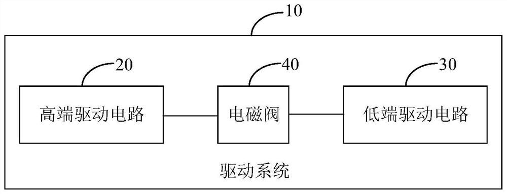
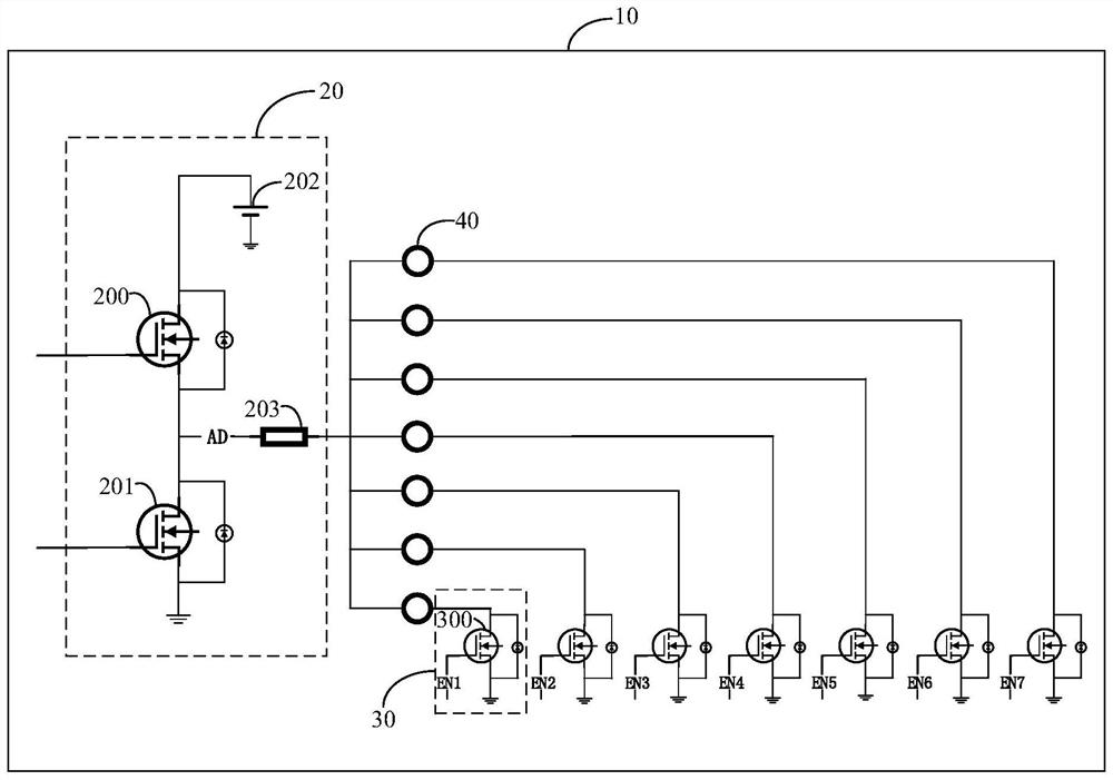
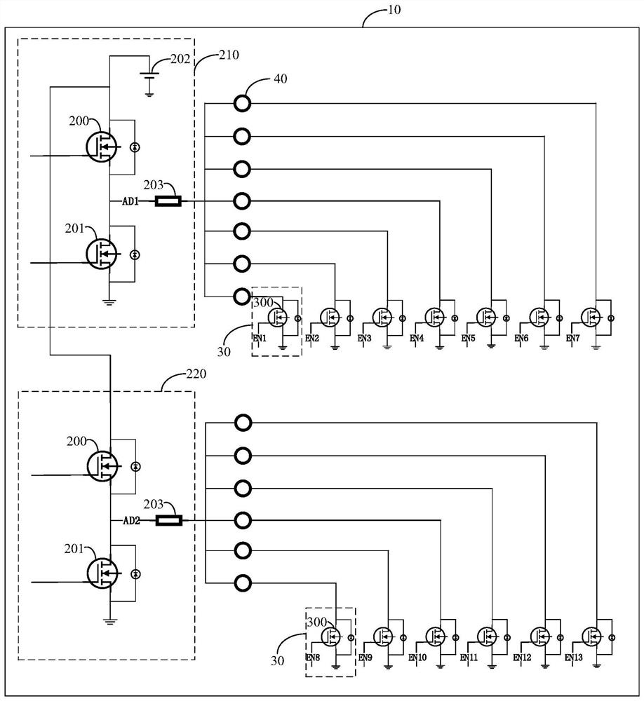
The invention provides a driving circuit, a driving system, a driving method and a gearbox, the driving circuit comprises at least one high-end driving circuit and a plurality of low-end driving circuits corresponding to the high-end driving circuits, and the signal input ends of the high-end driving circuits are used for receiving electromagnetic valve driving control signals. The signal output end of the high-end drive circuit is used for being connected with the first end of each electromagnetic valve, the second end of each electromagnetic valve is used for being connected with the first output end of the low-end drive circuit, the second output end of the low-end drive circuit is grounded, and the input end of the low-end drive circuit is used for receiving enable control signals. Allthe electromagnetic valves share a high-end driving source, so that the energy storage of the consumption coil is also carried out in a common push-pull circuit, the cost is saved, and the protectionis shared; herein, the high end can realize normally-pulled high level, and can also send duty ratio variable PWM waveforms in real time, so that all electromagnetic valves achieve consistent drivingcurrent, high-end control resources are saved, and the complexity of software control is reduced.

Description

technical field [0001] The invention relates to the technical field of solenoid valve drive, in particular to a drive circuit, a drive system, a drive method and a gearbox. Background technique [0002] For the electro-mechanical automatic mechanical transmission (Automated Mechanical Transmission, AMT), the solenoid valve can directly and conveniently drive the gear shifting and clutch actuators. At the same time, the solenoid valve facilitates the realization of automation and intelligent control algorithms to improve the use of the gearbox. life. [0003] However, in the existing technology, a solenoid valve corresponds to a high-end control and a low-end control, which increases the control cost. The high-end controls the power supply and the low-end controls the PWM waveform. When controlling the inductive load of the solenoid valve, it is easy to generate coil energy storage. , especially for PWM-controlled high-speed switching solenoid valves, the requirements for th...

Claims


Application Information

Patent Timeline
Patent Type & Authority Applications(China)
IPC IPC(8): H02M1/088H02M1/32
CPCH02M1/088H02M1/32
Inventor 肖帅飞张亮何琪
Owner 湖南行必达网联科技有限公司
Learn More