Optical fiber arrangement device for computer
A computer and optical fiber technology, applied in the computer field, can solve the problems of increasing the use space of the optical fiber connection box, inconvenient line inspection and maintenance, waste of resource space, etc., to achieve the effect of ensuring the utilization rate of internal space, ensuring reasonable utilization, and simple operation
- Summary
- Abstract
- Description
- Claims
- Application Information
AI Technical Summary
Problems solved by technology
Method used
Image
Examples
Embodiment 1
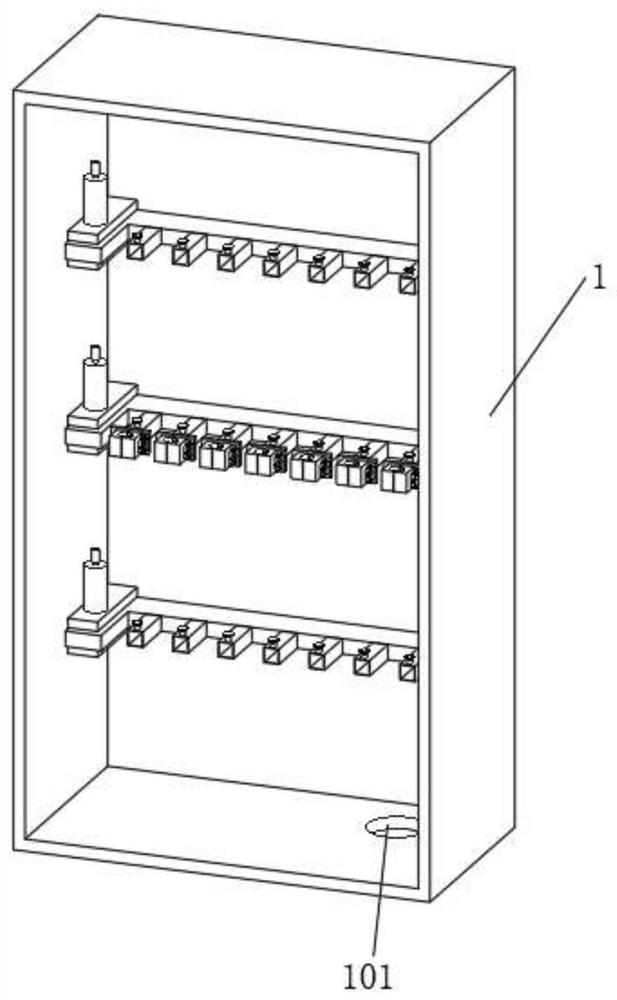
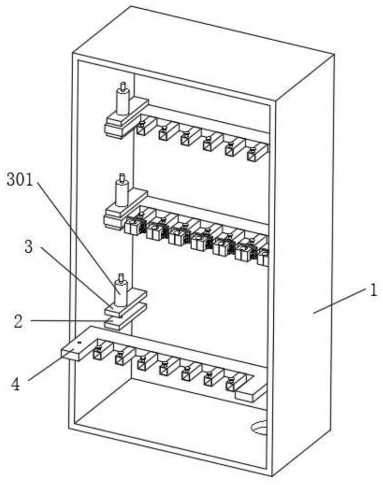
[0028] Embodiments of the present invention provide an optical fiber arrangement device for computers, such as Figure 1-7 As shown, it includes the main body 1 of the optical fiber connection box and the U-shaped clamping plate 4. The bottom of the main body 1 of the optical fiber connection box is provided with an optical fiber access opening 101, and the optical fiber cable can enter the interior of the main body 1 of the optical fiber connection box through the optical fiber access opening 101 in the outside world. Then arrange and fix accordingly.
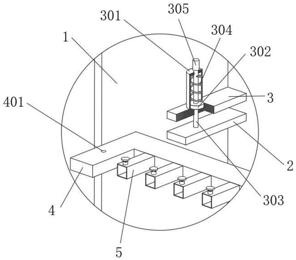
[0029] The two sides of the inner wall of the main body 1 of the optical fiber connection box are fixedly connected with the lower clamping rail 2 and the upper clamping rail 3, and the gap formed between the lower clamping rail 2 and the upper clamping rail 3 clamps the U-shaped clamping plate 4, and the U-shaped clamping The top of the board 4 is provided with a positioning hole 401, and the upper surface of the upper end ra...
Embodiment 2
[0037] Embodiments of the present invention provide an optical fiber arrangement device for computers, such as Figure 1-7 As shown, it includes the main body 1 of the optical fiber connection box and the U-shaped clamping plate 4. The bottom of the main body 1 of the optical fiber connection box is provided with an optical fiber access opening 101. Rail 3, the gap formed between the lower end clamping rail 2 and the upper end clamping rail 3 clamps the U-shaped clamping plate 4, and the top of the U-shaped clamping plate 4 is provided with a positioning clamping hole 401, and the upper surface of the upper end clamping rail 3 is provided with There is a clamping mechanism corresponding to the U-shaped clamping plate 4. The front “U” groove of the U-shaped clamping plate 4 is fixedly connected with multiple groups of hollow square columns 5, and the front of the hollow square column 5 is provided with a square slot. A sliding square column 601 is movably inserted into the squa...
Embodiment 3
[0043] Embodiments of the present invention provide an optical fiber arrangement device for computers, such as Figure 1-7 As shown, it includes the main body 1 of the optical fiber connection box and the U-shaped clamping plate 4. The bottom of the main body 1 of the optical fiber connection box is provided with an optical fiber access opening 101. Rail 3, the gap formed between the lower end clamping rail 2 and the upper end clamping rail 3 clamps the U-shaped clamping plate 4, and the top of the U-shaped clamping plate 4 is provided with a positioning clamping hole 401, and the upper surface of the upper end clamping rail 3 is provided with There is a clamping mechanism corresponding to the U-shaped clamping plate 4. The front “U” groove of the U-shaped clamping plate 4 is fixedly connected with multiple groups of hollow square columns 5, and the front of the hollow square column 5 is provided with a square slot. A sliding square column 601 is movably inserted into the squa...
PUM
 Abstract
Description
Claims
Application Information
 - Generate Ideas
- Intellectual Property
- Life Sciences
- Materials
- Tech Scout
- Unparalleled Data Quality
- Higher Quality Content
- 60% Fewer Hallucinations
Browse by: Latest US Patents, China's latest patents, Technical Efficacy Thesaurus, Application Domain, Technology Topic, Popular Technical Reports.
© 2025 PatSnap. All rights reserved.Legal|Privacy policy|Modern Slavery Act Transparency Statement|Sitemap|About US| Contact US: help@patsnap.com


