
An anti-falling device for oil pipes used in oilfield development

A technology for preventing shedding and tubing, which is applied in the direction of drill pipe, casing, earthwork drilling, etc. It can solve the problems of production stoppage, shedding, loose buckle, etc., and achieve the effect of increasing work efficiency, increasing stability, and convenient disassembly and assembly

Active Publication Date: 2021-02-02
CHINA PETROLEUM & CHEM CORP +1
View PDF15 Cites 0 Cited by
  • Summary
  • Abstract
  • Description
  • Claims
  • Application Information

AI Technical Summary

Problems solved by technology

[0003] With the rapid development of social economy, the demand for oil is gradually increasing. In the current recovery methods of oil fields, pumping units still occupy a large proportion. The outer layer of the oil well is casing, and the casing and casing are sealed with cement. The space on the well wall allows the casing to be fixed in the downhole. There is an oil pipe suspended at the wellhead in the casing. The structure is relatively simple. In the case of long-term oil pumping, the oil pipe connection will become loose and fall off.
If it falls off, the production operation needs to be stopped, which will seriously affect the production. Therefore, it is necessary to improve the installation structure of the oil pipe. At the same time, the present invention proposes an oil pipe anti-falling device for oilfield development, which is convenient to better solve the above-mentioned problems.

Method used

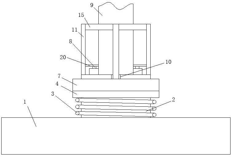

Image

  • An anti-falling device for oil pipes used in oilfield development
  • An anti-falling device for oil pipes used in oilfield development
  • An anti-falling device for oil pipes used in oilfield development

Examples


Embodiment Construction

[0025] In order to make the object, technical solution and advantages of the present invention clearer, the present invention will be further described in detail below in conjunction with the accompanying drawings and embodiments. It should be understood that the specific embodiments described here are only used to explain the present invention, not to limit the present invention.

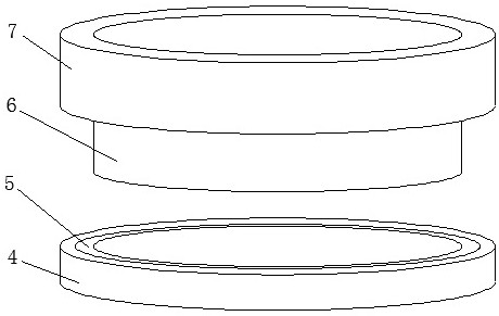
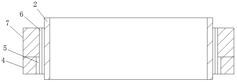
[0026] refer to Figure 1-5, an anti-falling device for oil pipes used in oil field development, comprising a pumping unit body 1, characterized in that: the top of the pumping unit body 1 is fixedly installed with a connecting oil pipe 2 connected through it, and a spring sleeve 3 is movably sleeved on the connecting oil pipe 2 And internal thread sleeve 6, it is convenient for spring sleeve 3 to drive limit ring 4 and rotating wrist ring 7 to move up and down. The bottom end of spring sleeve 3 is fixedly connected to the top of pumping unit body 1, and the bottom of internal thread sleeve 6 is ro...


PUM


Abstract

The invention belongs to the technical field of oil pipe anti-falling devices, and particularly discloses an oil pipe anti-falling device for oil field exploitation. The oil pipe anti-falling device comprises an oil pumping unit body, wherein a connecting oil pipe which is connected in a penetrating mode is fixedly installed at the top of the oil pumping unit body; a spring sleeve and an internalthread sleeve are movably connected to the connecting oil pipe in a sleeving mode; a limiting ring is installed below the internal thread sleeve through a rotating bearing; the spring sleeve is connected to the connecting oil pipe in a sleeving mode; the rotating bearing is fixedly installed inside the limiting ring, so that the rotating bearing can conveniently drive the internal thread sleeve and a rotating hand ring to rotate; a movable groove is formed in the outer wall of the upper part of the connecting oil pipe, so that a limiting plate can conveniently perform overturning motion insidethe movable groove; threaded teeth are arranged below the outer wall of the limiting plate, so that the internal thread sleeve can be conveniently connected to the threaded teeth in a threaded mode,and then the position of the limiting plate can be limited and fixed; and meanwhile, under the action of the spring sleeve, the stability of the internal thread sleeve in threaded connection to the threaded teeth is improved.

Description

technical field [0001] The invention belongs to the technical field of an oil pipe anti-falling device, in particular to an oil pipe anti-falling device for oil field development. Background technique [0002] Petroleum refers to a mixture of gaseous, liquid and solid hydrocarbons in natural occurrence. Petroleum is divided into crude oil, natural gas, natural gas liquid and natural tar, etc., but it is customary to use "oil" as the definition of "crude oil". Petroleum is a viscous, dark brown liquid known as the "blood of industry". There are oil reserves in some areas of the upper crust, and the main components are mixtures of various alkanes, cycloalkanes, and aromatic hydrocarbons, which are one of the main objects of geological exploration. The oil-forming mechanism of petroleum has two theories of biosedimentary oil and petrochemical oil. The former is more widely accepted. It is believed that oil is formed by organisms in ancient oceans or lakes after a long evoluti...

Claims


Application Information

Patent Timeline
Patent Type & Authority Patents(China)
IPC IPC(8): E21B19/16E21B17/02
CPCE21B17/02E21B19/16
Inventor 姚秀田王明鹏马军高薪
Owner CHINA PETROLEUM & CHEM CORP
Learn More