Sieve shaker

A technology of screen machine and material storage cavity, applied in the field of shaker screen machine, can solve the problems of large space occupied by shaker screen machine, increase production cost, increase the space occupied by mechanism, etc., achieve compact structure, increase production efficiency and occupy more space. small space effect

Active Publication Date: 2020-12-11
四川大学锦城学院
View PDF16 Cites 5 Cited by
  • Summary
  • Abstract
  • Description
  • Claims
  • Application Information

AI Technical Summary

Problems solved by technology

[0002] Shaking sieve machines are widely used in all walks of life. Most of the sieving machines in the prior art include a sieve bed, and the structure of shaking sieve parts is arranged at the bottom of the sieve bed. This structure makes the screen shaker occupy a large space, and when multi-stage filtration is required, it can only be achieved by adding a sieve bed, which not only increases the space occupied by the mechanism, but also increases the production cost

Method used


Image

  • Sieve shaker
  • Sieve shaker
  • Sieve shaker

Examples


Embodiment Construction

[0029] The technical solutions of the present invention will be clearly and completely described below in conjunction with the accompanying drawings. Apparently, the described embodiments are some of the embodiments of the present invention, rather than all of them. Based on the embodiments of the present invention, all other embodiments obtained by persons of ordinary skill in the art without making creative efforts belong to the protection scope of the present invention.

[0030] In the description of the present invention, it should be understood that the orientation or positional relationship indicated by the terms "upper", "lower", "front", "rear", "inner", "outer" etc. Orientation or positional relationship is only for the convenience of describing the present invention and simplifying the description, and does not indicate or imply that the referred device or element must have a specific orientation, be constructed and operated in a specific orientation, and thus should ...


PUM


Abstract

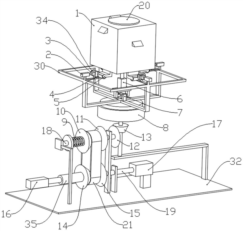
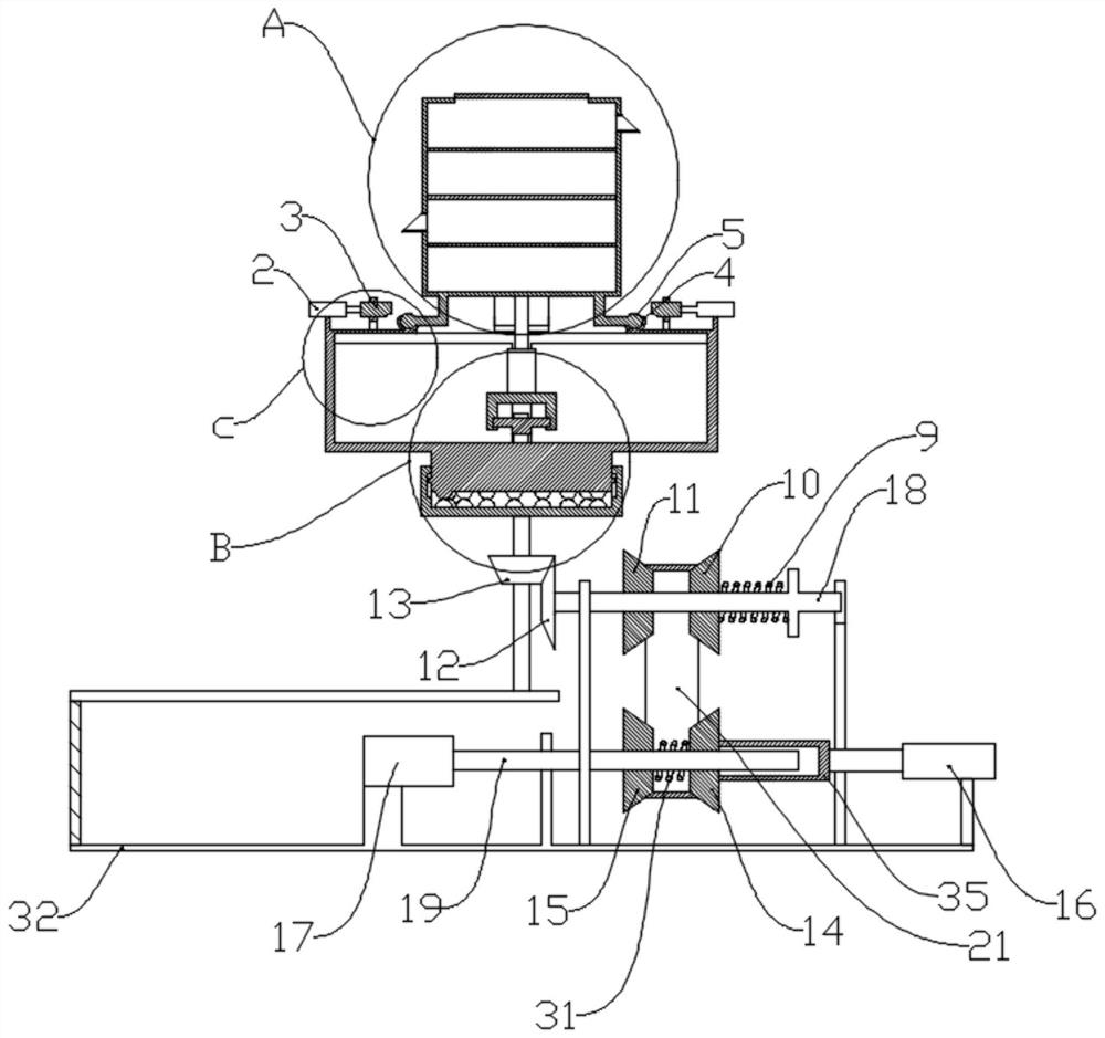
The invention discloses a sieve shaker. The sieve shaking machine comprises a storage cavity and a supporting frame; the storage cavity is of a hollow cavity structure, and a filter screen is arrangedin the storage cavity; the interior of the storage cavity is divided into a plurality of cavities by the filter screen, and the mesh number of the filter screen is gradually increased from top to bottom; four rotating shafts A are arranged at the bottom of the storage cavity; the supporting frame is provided with a supporting block, a pressing block and a first hydraulic cylinder corresponding tothe rotating shafts A; a through groove A is arranged on the supporting block, the inner wall of the through groove A is in sliding fit with the side walls of the rotating shafts A; a cylinder body of the first hydraulic cylinder is connected with the supporting frame, and a piston rod of the first hydraulic cylinder is connected with the pressing block; the supporting frame is provided with a second hydraulic cylinder, a piston rod of the second hydraulic cylinder is coaxial with the storage cavity, a cylinder body of the second hydraulic cylinder is connected with the supporting frame through a universal joint coupling, and the piston rod of the second hydraulic cylinder is connected with the storage cavity through a spherical universal joint, so that the storage cavity rotates around acertain rotating shaft A; a discharging channel is arranged in the storage cavity; and a sieve shaking mechanism is arranged at the bottom of the supporting frame. The device of the invention can perform multi-stage screening at the same time.

Description

technical field [0001] The invention relates to the field of shaking screen machines, in particular to a shaking screen machine. Background technique [0002] Shaking sieve machines are widely used in all walks of life. Most of the sieving machines in the prior art include a sieve bed, and the structure of shaking sieve parts is arranged at the bottom of the sieve bed. This structure makes the screen shaker occupy a large space, and when multi-stage filtration is required, it can only be realized by adding a sieve bed, which not only increases the space occupied by the mechanism, but also increases the production cost. Contents of the invention [0003] In view of the above-mentioned shortcomings of the prior art, the purpose of the present invention is to provide a shaking screen machine capable of multi-stage screening and increase production efficiency. [0004] In order to realize the above-mentioned purpose of the invention, the present invention provides the followi...

Claims


Application Information

Patent Timeline
IPC IPC(8): B07B1/28B07B1/42B07B1/46
CPCB07B1/28B07B1/42B07B1/46B07B2201/04
Inventor 赵汝和李小平谭驰骋赵郅涛
Owner 四川大学锦城学院
Why Eureka
Try Eureka