Moxibustion equipment suitable for realizing various moxibustion therapy modes without hand holding
A hand-held, moxibustion-free technology, applied in physical therapy, heating/cooling reflective point instruments, etc., can solve problems such as operator burns, operator fatigue, patients with unsatisfactory moxibustion effects, etc., to enhance the effect and reduce the scope Effect
- Summary
- Abstract
- Description
- Claims
- Application Information
AI Technical Summary
Problems solved by technology
Method used
Image
Examples
Embodiment 1
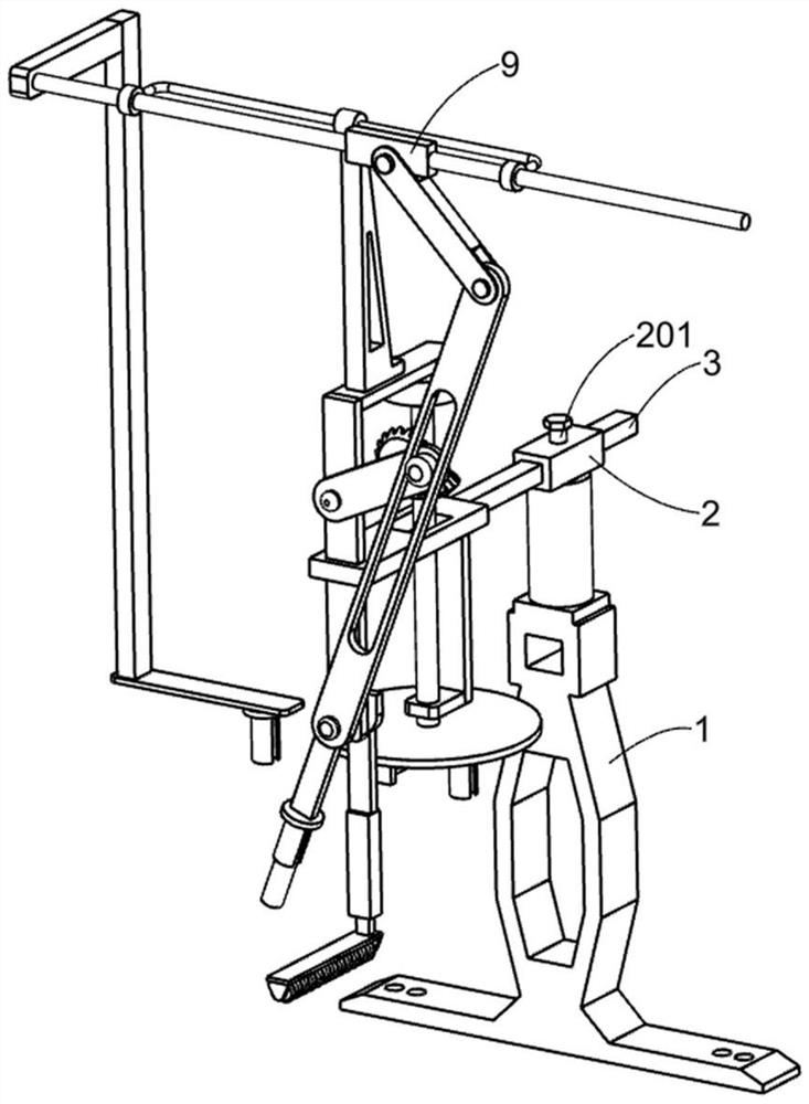
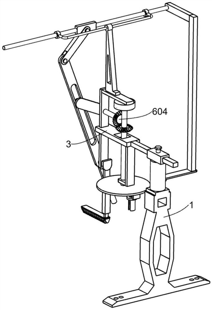
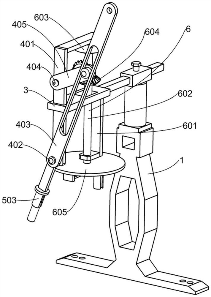
[0025] A moxibustion device suitable for realizing various moxibustion methods without holding hands, such as Figure 1-8 As shown, it includes a support 1, a sliding sleeve 2, a first fastening bolt 201, a sliding support frame 3, a moxibustion simulation mechanism 4, a moxa stick clamping mechanism 5 and a rotary moxibustion simulation mechanism 6. The sleeve 2 is fixed on the upper end of the support 1 and a threaded hole is opened on the sliding sleeve 2, the sliding support frame 3 is slidably arranged in the sliding sleeve 2, and the first fastening bolt 201 is rotatably arranged in the sliding sleeve 2 and one end of the first fastening bolt 201 is in contact with the sliding support frame 3. The first fastening bolt 201 is used to adjust the position of the sliding support frame 3 and limit it. The sparrow pecking moxibustion simulation mechanism 4 for treating patients with sparrow pecking moxibustion is set on the sliding support frame 3, and the rotary rotary moxibu...
Embodiment 2
[0033] On the basis of Example 1, such as figure 1 and Figure 6 As shown, it also includes a support seat 7, a support sliding sleeve 8, a movable rod 9, a swing rod 10 and a connecting frame 11. The support seat 7 is fixed on the upper side of the first L-shaped mounting plate 401, and the support Sliding sleeve 8 is fixedly arranged on the upper end of support seat 7, and described movable rod 9 is slidably arranged in the supporting sliding sleeve 8, and described swinging rod 10 is rotatably arranged on the upper end of swinging slot rod 403 and the upper end of swinging rod 10 is in contact with the movable Rod 9 is rotatably connected, and the swing groove rod 403 can drive the movable rod 9 to move left and right repeatedly through the swing rod 10. The connecting frame 11 is fixed on one end of the movable rod 9 and the bottom side of the connecting frame 11 is provided with moxa sticks. Clamping mechanism 5.
[0034] Specific use process: when the patient needs to ...
Embodiment 3
[0036] On the basis of Example 2, such as Figure 7-8 As shown, it also includes a swing slotted rod 12, a compression spring 13 and a massage roller 14. The swing slotted rod 12 is fixed on the other end of the first transmission shaft 402 and a chute is provided on the swing slotted rod 12. The swinging slotted rod 12 is close to the rotating disk 605, and the massage roller 14 used for massage operation around the patient's acupuncture points is slidably arranged in the chute on the swinging slotted rod 12. One end of the massage roller 14 A compression spring 13 is arranged between the swing slotted rod 12 .
[0037] Specific use process: the swing grooved rod 403 will drive the swing grooved rod 12 to move left and right through the first transmission shaft 402, and the swing grooved rod 12 will drive the massage roller 14 to move left and right, and the massage roller 14 can massage around the acupuncture points of the patient The operation makes the patient more relaxe...
PUM
 Abstract
Description
Claims
Application Information
 - R&D
- Intellectual Property
- Life Sciences
- Materials
- Tech Scout
- Unparalleled Data Quality
- Higher Quality Content
- 60% Fewer Hallucinations
Browse by: Latest US Patents, China's latest patents, Technical Efficacy Thesaurus, Application Domain, Technology Topic, Popular Technical Reports.
© 2025 PatSnap. All rights reserved.Legal|Privacy policy|Modern Slavery Act Transparency Statement|Sitemap|About US| Contact US: help@patsnap.com


