H-shaped hollow anti-slide pile
An anti-slide pile, hollow technology, applied to sheet pile walls, excavation, construction, etc., can solve the problems of increasing the amount of concrete, wasting building materials, increasing the cost of piles, etc., to reduce construction costs, save concrete, and reduce construction costs. effect of difficulty
- Summary
- Abstract
- Description
- Claims
- Application Information
AI Technical Summary
Problems solved by technology
Method used
Image
Examples
Embodiment 1
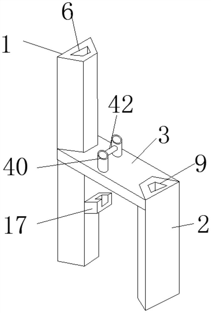
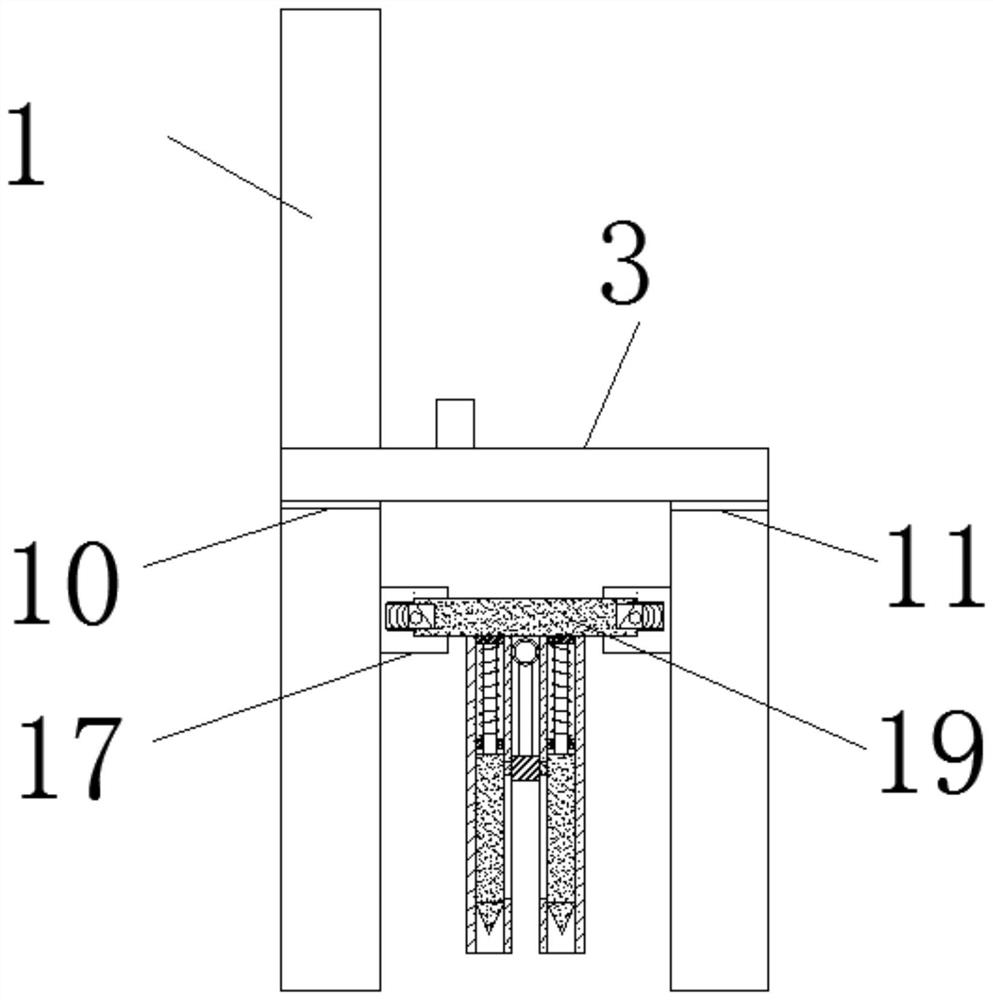
[0040] see Figure 1-12, an h-shaped hollow anti-slide pile according to an embodiment of the present invention, comprising a front pile 1 and a rear pile 2, a beam 3 is connected between the front pile 1 and the rear pile 2, and the front pile 1 includes a pile Front-end-4 and pile rear-end-5, the thickness of pile front-end-4 exceeds pile rear-end-5, and hollow hole-6 is arranged between described pile front-end-4 and described pile rear-end-5, and described rear pile 2 includes pile front end 2 7 and pile rear end 2 8, the thickness of pile front end 2 7 is greater than pile rear end 2 8, and a hollow hole 2 9 is arranged between the pile front end 2 7 and the pile rear end 2 8, so The front pile 1 is provided with a front pile projection 10 near the crossbeam 3, and the rear pile 2 is provided with a rear pile projection 11 near the crossbeam 3. The front pile projection 10 and the rear pile projection Blocks 11 are located below the beam 3, the bottoms of the front pile ...
Embodiment 2
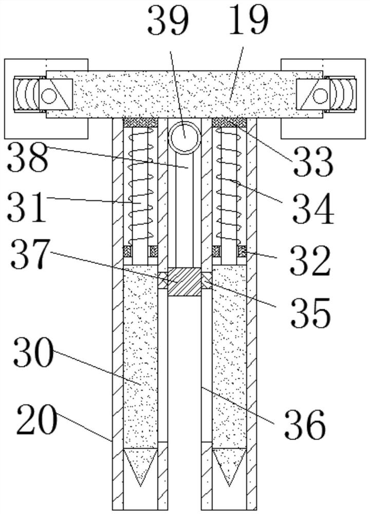
[0042] see Figure 1-5 , the stabilizing mechanism includes a connection block one 17, a groove one 18, a cross bar 19 and a stabilizing sleeve 20, the pile rear end one 5 and the pile front end two 7 are fixedly connected with a connection block one 17, and the connection The top of block one 17 has groove one 18, is provided with cross bar 19 and the port of described cross bar 19 is positioned at described groove one 18 between described connection block one 17, and the bottom of described cross bar 19 is fixed A stabilizing sleeve 20 is connected, a connecting mechanism is arranged between the connecting block one 17 and the cross bar 19, a telescoping mechanism is provided inside the stabilizing sleeve 20, and the connecting mechanism includes a groove two 21, a spring one 22 , movable block 23 and connecting groove one 24, the inner wall of described groove one 18 has groove two 21, the inside of described groove two 21 is connected with movable block 23 by spring one 22...
Embodiment 3
[0044] see Figure 1-5 , the telescoping mechanism includes a movable rod 30, a connecting rod one 31, a fixed block 32, a moving block 33 and a spring two 34, and the inside of the stable sleeve 20 is provided with a movable rod 30, and the movable rod 30 and the stable sleeve 20, the top of the movable rod 30 is fixedly connected with a connecting rod 31, and the top of the connecting rod 31 is fixedly connected with a moving block 33, and the inside of the stable sleeve 20 is fixedly connected with a fixed block 32. The connecting rod one 31 runs through the fixed block 32, and a spring two 34 is connected between the fixed block 32 and the moving block 33, and the spring two 34 is wrapped around the outer surface of the connecting rod one 31. One side of the movable rod 30 is fixedly connected to the second limit block 35, and the stable sleeve 20 opens a limit groove two 36 near the second limit block 35, and the second limit block 35 is located at the second limit groove...
PUM
 Abstract
Description
Claims
Application Information
 - R&D
- Intellectual Property
- Life Sciences
- Materials
- Tech Scout
- Unparalleled Data Quality
- Higher Quality Content
- 60% Fewer Hallucinations
Browse by: Latest US Patents, China's latest patents, Technical Efficacy Thesaurus, Application Domain, Technology Topic, Popular Technical Reports.
© 2025 PatSnap. All rights reserved.Legal|Privacy policy|Modern Slavery Act Transparency Statement|Sitemap|About US| Contact US: help@patsnap.com


