
Sliding type steel support erecting device

A steel support and sliding technology, applied in the field of steel support installation, can solve the problems of complex hoisting of steel supports, and achieve the effects of saving man-hours, increasing accuracy and convenience, and fast and precise positioning

Active Publication Date: 2020-12-08
TONGJI UNIV
View PDF9 Cites 1 Cited by
  • Summary
  • Abstract
  • Description
  • Claims
  • Application Information

AI Technical Summary

Problems solved by technology

[0004] The purpose of the present invention is to provide a sliding type steel support erection device, after the steel support is hoisted, the steel support can be quickly and accurately positioned by directional sliding, so as to solve the problem of complicated hoisting of the steel support in the pit

Method used


Image

  • Sliding type steel support erecting device
  • Sliding type steel support erecting device
  • Sliding type steel support erecting device

Examples


Embodiment

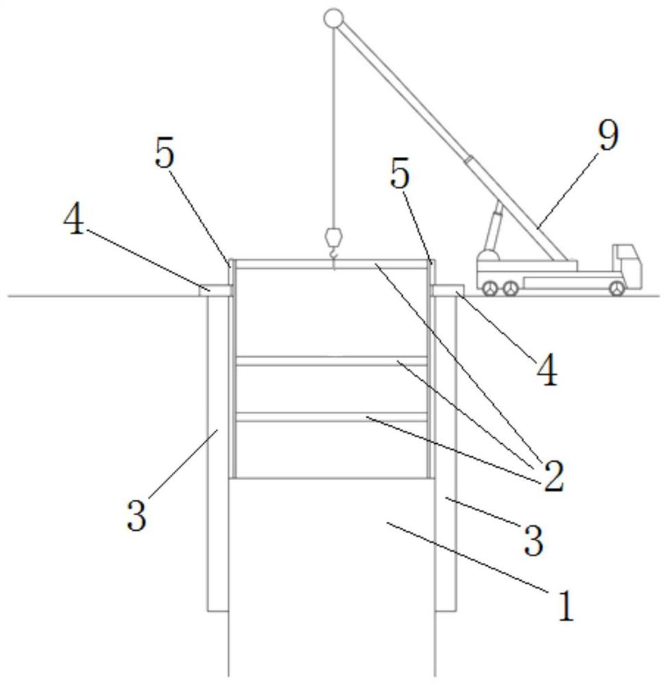
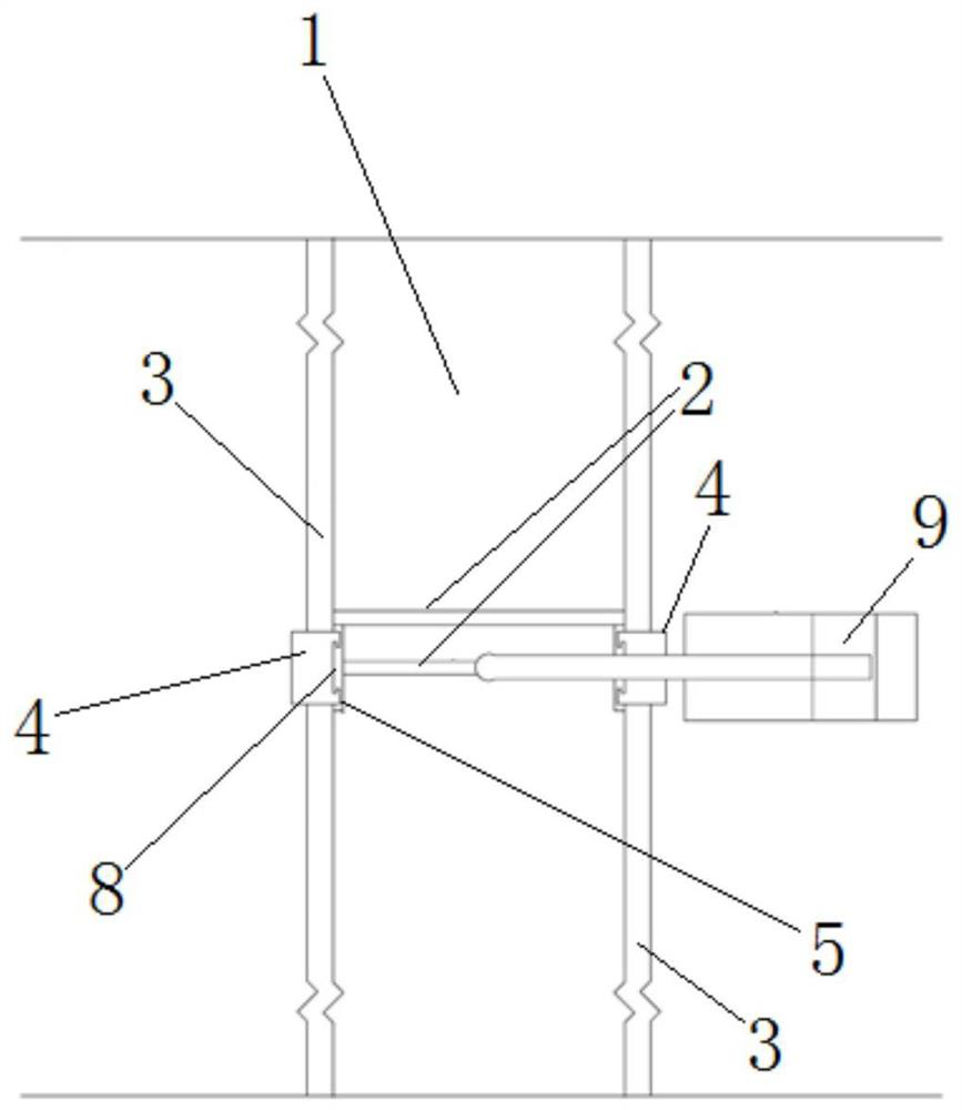
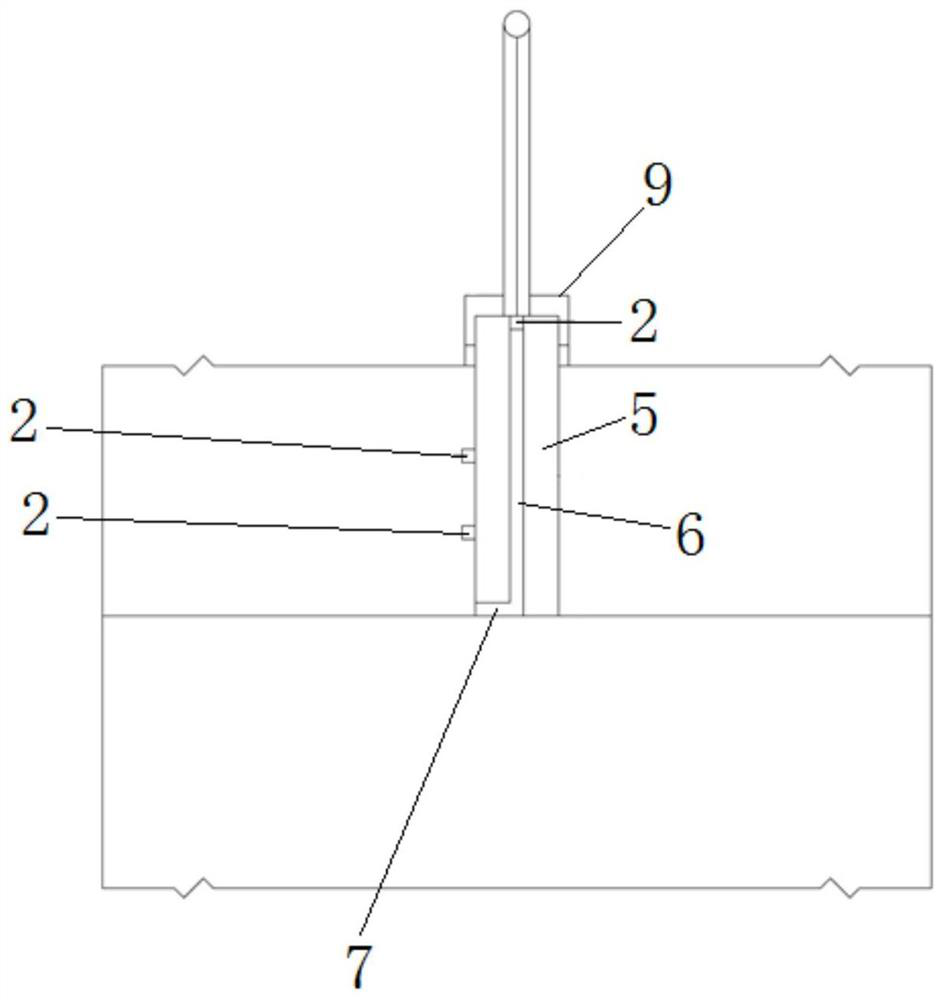
[0033] Such as figure 1 , figure 2 , image 3 A sliding type steel support erection device is shown, the device is arranged in the foundation pit 1, and the device includes a pair of sliding guide units that are arranged oppositely and respectively adapted to the two ends of the steel support 2. The sliding guide units include The retaining wall 3 in the foundation pit 1, the fixed block 4 that is arranged on the top of the retaining wall 3 and the sliding guide block 5 that is vertically arranged on the side of the fixed block 4 and extends into the foundation pit 1, the side of the sliding guide block 5 A steel support and guide mechanism is provided, and the end of the steel support 2 is slidably arranged in the steel support and guide mechanism.

[0034] Wherein, the retaining wall 3 is embedded in the inner side wall of the foundation pit 1 , and the top surface of the retaining wall 3 is flush with the top surface of the foundation pit 1 .

[0035] Such as Figure 4...


PUM


Abstract

The invention relates to a sliding type steel support erecting device. The device is arranged in a foundation pit and comprises a pair of downward sliding guide units which are oppositely arranged andmatched with the two ends of a steel support respectively. Each downward sliding guide unit comprises a retaining wall arranged in the foundation pit, a fixing block arranged at the top of the retaining wall and a downward sliding guide block vertically arranged at one side of the fixing block and extending into the foundation pit, a steel support guide mechanism is arranged on the side face of each downward sliding guide block, and the end of the steel support is arranged in the steel support guide mechanisms in a sliding manner. Compared with the prior art, by arranging the pair of downwardsliding guide units, vertical guide and height positioning are conducted on the two ends of the steel support, rapid and accurate positioning is achieved when the steel support is hoisted, the erecting process of the steel support is simplified, and the stability in the hoisting process is guaranteed.

Description

technical field [0001] The invention belongs to the technical field of steel support installation, and relates to a sliding type steel support erection device. Background technique [0002] With the accelerated development of my country's urbanization process, the contradiction between the growing demand for urban space and limited land resources has become increasingly prominent, and the development and utilization of urban underground space has become one of the key points of current urban infrastructure construction. Zhongzheng has more and more foundation pit projects. In the construction of deep foundation pits, the installation of steel supports is a very important step. Whether the installation of steel supports can be quickly and accurately realized is a key issue in construction. In the current steel support installation process, the crane is mainly used to hoist the steel support in the pit. The hoisting positioning and installation are relatively complicated. Duri...

Claims


Application Information

Patent Timeline
IPC IPC(8): E02D17/04E04G21/14E04G21/18
CPCE02D17/04E04G21/14E04G21/18
Inventor 木林隆黄茂松钱建固
Owner TONGJI UNIV
Learn More