Portable energy storage battery pack placement base

A technology for placing bases and battery packs, applied to battery pack components, circuits, electrical components, etc., can solve the problems of inconvenient disassembly and installation of battery packs, unstable battery pack placement, and reduced use flexibility, and achieve increased shock absorption. Protection, increase the convenience of disassembly and installation, and increase the effect of shock absorption and high efficiency

Pending Publication Date: 2020-12-04
湖南衡盈电子科技有限公司
View PDF7 Cites 0 Cited by
  • Summary
  • Abstract
  • Description
  • Claims
  • Application Information

AI Technical Summary

Problems solved by technology

Using the battery as an energy source can obtain stable voltage, stable current, stable power supply for a long time, and a current that is less affected by the outside world, and the battery structure is simple, the charging and discharging operation is simple and easy, and it is not affected by the external climate and temperature. Stable and reliable, when the battery pack is used, the base needs to be used. 1. In the existing battery pack base, because the base is a fixed structure, it is inconvenient to disassemble and install the base of the battery pack. 2. In the existing battery pack placement base device, because the base needs to move its position during placement or use, it will cause shock to the battery pack when it is placed again in the moved position, resulting in vibration when the battery pack is placed. Unstable, at the same time there is a shock phenomenon, and it is not easy to carry when the base moves; therefore, we propose a new type of portable energy storage battery pack placed on the base

Method used


Image

  • Portable energy storage battery pack placement base
  • Portable energy storage battery pack placement base
  • Portable energy storage battery pack placement base

Examples


Embodiment Construction

[0020] In order to make the technical means, creative features, goals and effects achieved by the present invention easy to understand, the present invention will be further described below in conjunction with specific embodiments.

[0021] In the description of the present invention, it should be noted that the terms "upper", "lower", "inner", "outer", "front end", "rear end", "both ends", "one end", "another end" The orientation or positional relationship indicated by etc. is based on the orientation or positional relationship shown in the drawings, and is only for the convenience of describing the present invention and simplifying the description, rather than indicating or implying that the referred device or element must have a specific orientation, use a specific Azimuth configuration and operation, therefore, should not be construed as limiting the invention. In addition, the terms "first" and "second" are used for descriptive purposes only, and should not be understood ...


PUM


Abstract

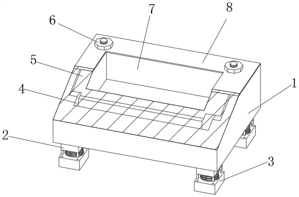
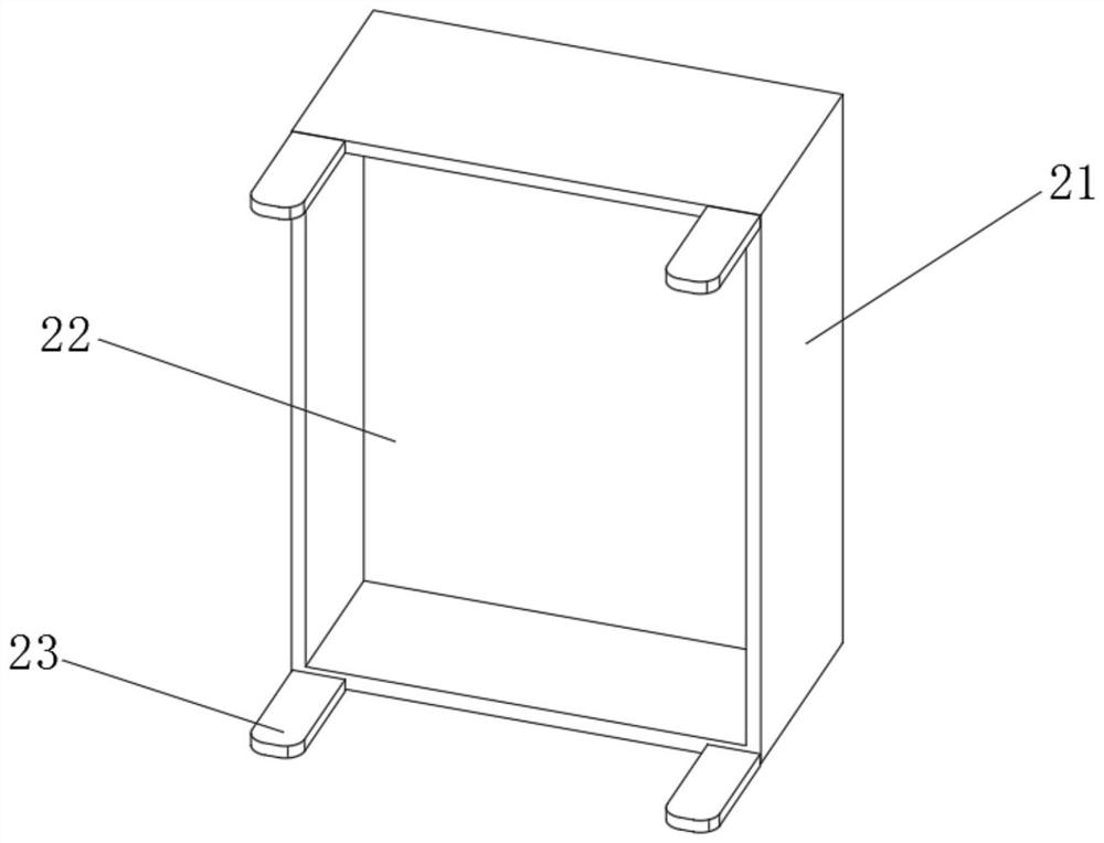
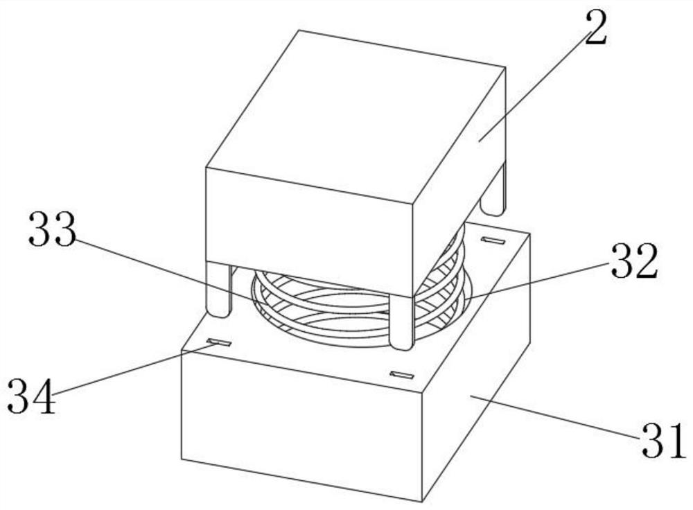
The invention discloses a portable energy storage battery pack placement base, which comprises a device main body, wherein connecting structures are fixedly connected to the four corners of the lowerend of the device main body, damping structures are fixedly connected to the lower ends of the four connecting structures, a U-shaped clamping groove is formed in the device main body, a U-shaped dismounting plate is mounted in the U-shaped clamping groove, a protection plate is arranged at the upper end of the device body, fixing screws are connected to the four corners of the upper end of the device body in a threaded mode, the device body, the U-shaped dismounting plate and the protection plate are connected together through the fixing screws, and a first accommodating groove penetrating upand down is formed in the middle of the upper end of the protection plate. According to the portable energy storage battery pack placement base, by arranging the connecting structure, the damping structure and the U-shaped dismounting plate, the damping protection performance is improved, the damping efficiency is improved for use of the device main body, the influence of external vibration on the interior of the storage battery pack is avoided, and the easy dismounting, easy mounting and easy portability of the device main body are further improved.

Description

technical field [0001] The invention relates to the technical field of energy storage battery packs, in particular to a base for placing a portable energy storage battery pack. Background technique [0002] As technology advances, batteries generally refer to small devices that can generate electricity. Such as solar cells. The performance parameters of the battery mainly include electromotive force, capacity, specific energy and resistance. Using the battery as an energy source can obtain stable voltage, stable current, stable power supply for a long time, and a current that is less affected by the outside world, and the battery structure is simple, the charging and discharging operation is simple and easy, and it is not affected by the external climate and temperature. Stable and reliable, when the battery pack is used, the base needs to be used. 1. In the existing battery pack base, because the base is a fixed structure, it is inconvenient to disassemble and install the...

Claims


Application Information

Patent Timeline
IPC IPC(8): H01M2/10F16F15/04
CPCF16F15/04
Inventor 崔长印
Owner 湖南衡盈电子科技有限公司
Why Eureka
Try Eureka