
Belt body braking type shaft body pulling device

A shaft and system technology, applied in the directions of wrenches, manufacturing tools, wrenches, etc., can solve the problems of insufficient contact area between the wrench and the side of the shaft, the smooth surface of the side of the shaft cannot work, and the surface of the shaft is damaged. High strength, increase the blessing effect, increase the effect of friction

Active Publication Date: 2020-12-04
JIANGSU SIDA HEAVY IND
View PDF5 Cites 0 Cited by
  • Summary
  • Abstract
  • Description
  • Claims
  • Application Information

AI Technical Summary

Problems solved by technology

[0002] At present, the wrench is also a wrench. The existing wrench can only rotate the angular structure, and cannot work on the smooth surface of the shaft side. The main reason is that the contact area between the wrench and the side of the shaft is insufficient, resulting in the inability to rotate. At the same time, the low contact surface can also cause damage to the shaft surface

Method used

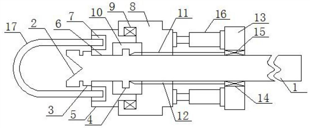

Image

  • Belt body braking type shaft body pulling device
  • Belt body braking type shaft body pulling device

Examples


Embodiment Construction

[0015] The following will clearly and completely describe the technical solutions in the embodiments of the present invention with reference to the accompanying drawings in the embodiments of the present invention. Obviously, the described embodiments are only some, not all, embodiments of the present invention. Based on the embodiments of the present invention, all other embodiments obtained by persons of ordinary skill in the art without making creative efforts belong to the protection scope of the present invention.

[0016] see figure 1 , an embodiment provided by the present invention: including a trigger lever 1, a main limiting plate 13 with a bearing mounting hole 14 in the center, a main threaded sleeve shell 8 with a main threaded hole 11 in the center, the trigger lever 1 A V-shaped groove 2 is provided at the center of one end of the V-shaped groove 2, and a first limit protrusion structure 3 of an integrated structure is provided on the side of one end of the trig...


PUM


Abstract

The invention discloses a belt body braking type shaft body pulling device. The belt body braking type shaft body pulling device comprises a pulling rod, a main limiting plate with a bearing mountinghole in the center, and a main threaded sleeve shell with a main threaded hole in the center. According to the belt body braking type shaft body pulling device, the mobility of a threaded structure isutilized to drive a brake belt to shrink, so that a clamping effect is formed on the surface of a shaft body, then the pressure of high-pressure air is utilized to limit the threaded structure, so that the pressure driving direction of the high-pressure air is opposite to the stress direction of the threaded structure from the brake belt, the clamping effect of the brake belt is improved, and therotation torque force with higher effect is provided; and meanwhile, due to the fact that the brake belt is arranged on the surface of the shaft body in a sleeving mode to provide pressure, the friction force between the side face of the shaft body and a component providing the rotation force can be effectively increased, the strength of the rotation torque is improved, meanwhile, the pressure between braking parts can be reduced, and the damage degree of the pressure to the surface of the shaft body during rotation is reduced.

Description

technical field [0001] The invention relates to the technical field of pulling devices, in particular to a belt braking type shaft pulling device. Background technique [0002] At present, the wrench is the wrench. The existing wrench can only rotate the angular structure, and cannot work on the smooth surface of the shaft side. The main reason is that the contact area between the wrench and the side of the shaft is insufficient, resulting in the inability to rotate. At the same time, the low contact surface can also cause damage to the shaft surface. Contents of the invention [0003] The object of the present invention is to provide a belt brake type shaft pulling device to solve the problems raised in the above-mentioned background technology. [0004] In order to achieve the above object, the present invention provides the following technical solutions: a brake-type shaft wrenching device, comprising a wrenching lever, a main limiting plate with a bearing mounting hol...

Claims


Application Information

Patent Timeline
Patent Type & Authority Applications(China)
IPC IPC(8): B25B13/48
CPCB25B13/48
Inventor 张娟
Owner JIANGSU SIDA HEAVY IND
Learn More