Array substrate, preparation method thereof and display panel

An array substrate and substrate substrate technology, which is applied in semiconductor/solid-state device manufacturing, electrical components, electrical solid-state devices, etc., can solve problems such as undercutting of laminated metal electrodes, and achieve the effect of avoiding poor display and packaging failure.

Pending Publication Date: 2020-11-27
WUHAN CHINA STAR OPTOELECTRONICS SEMICON DISPLAY TECH CO LTD
View PDF0 Cites 4 Cited by
  • Summary
  • Abstract
  • Description
  • Claims
  • Application Information

AI Technical Summary

Problems solved by technology

[0004] The present invention provides an array substrate and its preparation method as well as a display panel, so as to alleviate the technical problem of the undercut phenomenon of stacked metal electrodes in the existing array substrate

Method used


Image

  • Array substrate, preparation method thereof and display panel
  • Array substrate, preparation method thereof and display panel
  • Array substrate, preparation method thereof and display panel

Examples


Embodiment Construction

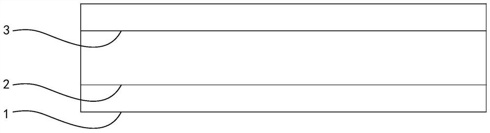
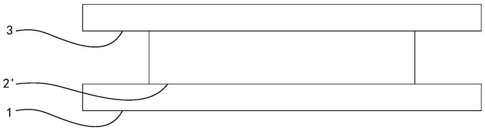
[0026] The description of the following embodiments refers to the attached drawings to illustrate specific embodiments in which the present invention can be implemented. The directional terms mentioned in the present invention, such as [up], [down], [front], [back], [left], [right], [inside], [outside], [side], etc., are for reference The direction of the additional schema. Therefore, the directional terms used are used to describe and understand the present invention, rather than to limit the present invention. In the figure, units with similar structures are indicated by the same reference numerals. In the drawings, the thickness of some layers and regions are exaggerated for clear understanding and ease of description. That is, the size and thickness of each component shown in the drawings are arbitrarily shown, but the present invention is not limited thereto.

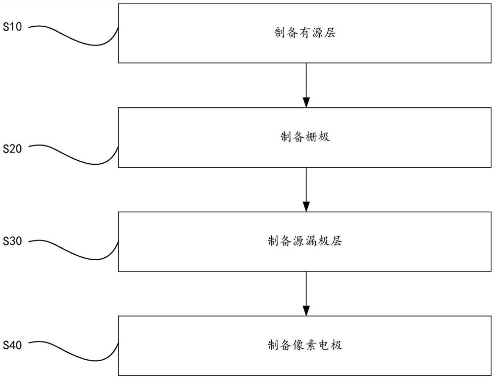
[0027] In one embodiment, a method for preparing an array substrate is provided, such as image 3 As shown, it i...


PUM


Abstract

The invention provides an array substrate, a preparation method thereof and a display panel. In the preparation method of the array substrate, a source-drain electrode layer is prepared by adopting alaminated metal layer. The laminated metal layer comprises a first metal layer, a second metal layer and a third metal layer which are laminated. The laminated metal layer is etched twice, so that inthe formed source electrode and drain electrode, the width of the third metal layer is smaller than or equal to the width of the second metal layer, and the width of the third metal layer is smaller than the width of the first metal layer. The problem that a laminated metal electrode in an existing array substrate has an undercut phenomenon is solved.

Description

Technical field [0001] The present invention relates to the field of display technology, in particular to an array substrate, a preparation method thereof, and a display panel. Background technique [0002] In the display panel array process, in order to balance the development and design requirements of the panel and the process characteristics, it is often necessary to use a laminated metal electrode structure. For example, in order to avoid the voltage drop of driving metal traces, usually aluminum (AL) with a small resistivity is selected as the trace metal. However, because aluminum has poor resistance to acid and alkali chemicals in the manufacturing process, such as figure 1 As shown, a top layer of titanium (Top Ti) 3 and a bottom layer of titanium (Bottom Ti) 1 are usually added to the upper and lower layers of the aluminum layer 2 to form a sandwich structure to ensure the stability of the metal electrode in the manufacturing process. However, in the subsequent array p...

Claims


Application Information

Patent Timeline
IPC IPC(8): H01L21/28H01L21/84H01L29/417H01L27/12H01L27/32
CPCH01L27/1259H01L29/401H01L27/1214H01L29/41733H10K59/12H10K59/1201H10K59/1213H01L27/1244G02F1/136222G02F1/1368H01L27/1222H01L27/127
Inventor 曹祖强戴超
Owner WUHAN CHINA STAR OPTOELECTRONICS SEMICON DISPLAY TECH CO LTD
Why Eureka
Try Eureka