
Full-automatic water quality analyzer and working method thereof

A water quality analyzer, fully automated technology, applied in the direction of analyzing materials, instruments, testing water, etc., can solve the problems of reducing labor intensity, inconvenient to carry, requiring manual sampling, etc., to achieve the effect of reducing labor intensity and convenient portability

Inactive Publication Date: 2020-11-27
安徽清大云博环保科技有限公司
View PDF14 Cites 6 Cited by
  • Summary
  • Abstract
  • Description
  • Claims
  • Application Information

AI Technical Summary

Problems solved by technology

[0003] The purpose of the present invention is to provide a fully automatic water quality analyzer and its working method. The present invention can place the water quality analyzer on the water surface of the sampling place through the hand handle, and the water quality analyzer floats through two buoyancy chambers at the bottom On the water surface, start three rotation motors, the output shaft of the rotation motors rotates forward and drives the transmission roller to rotate forward, and drives the three extrusion belts to rotate forward, and the three extrusion belts drive the sampling cylinder to descend, so that the sampling cylinder After entering the water, when the water surface is submerged in the bottom of the notch, the water enters the sampling cylinder through the notch, and the sampling is completed. The water quality analyzer can float in the water, and there is no need for manual lifting when sampling, which reduces labor intensity. The water quality analyzer can automatically Sampling solves the technical problems that traditional water quality analyzers require manual sampling, which is labor-intensive and not easy to carry;

Method used


Image

  • Full-automatic water quality analyzer and working method thereof
  • Full-automatic water quality analyzer and working method thereof
  • Full-automatic water quality analyzer and working method thereof

Examples


Embodiment Construction

[0034] The technical solutions of the present invention will be clearly and completely described below in conjunction with the embodiments. Apparently, the described embodiments are only some of the embodiments of the present invention, not all of them. Based on the embodiments of the present invention, all other embodiments obtained by persons of ordinary skill in the art without creative efforts fall within the protection scope of the present invention.

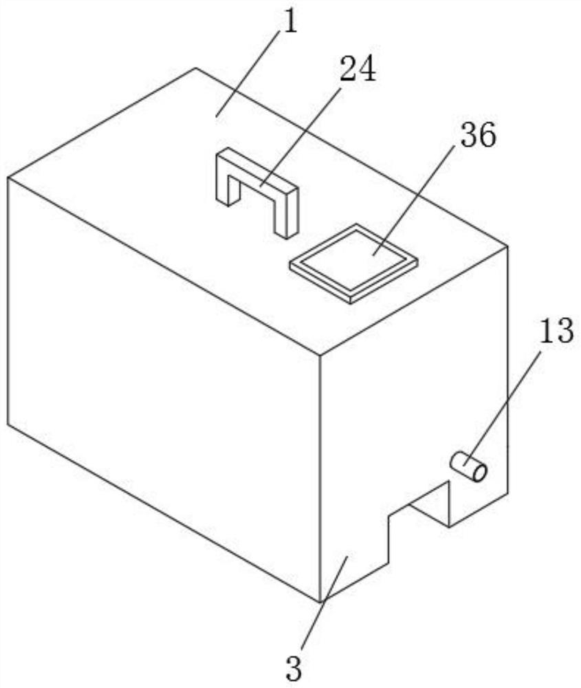
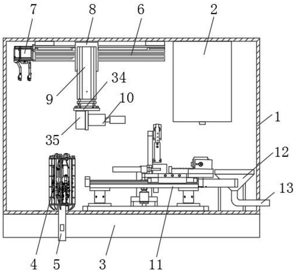
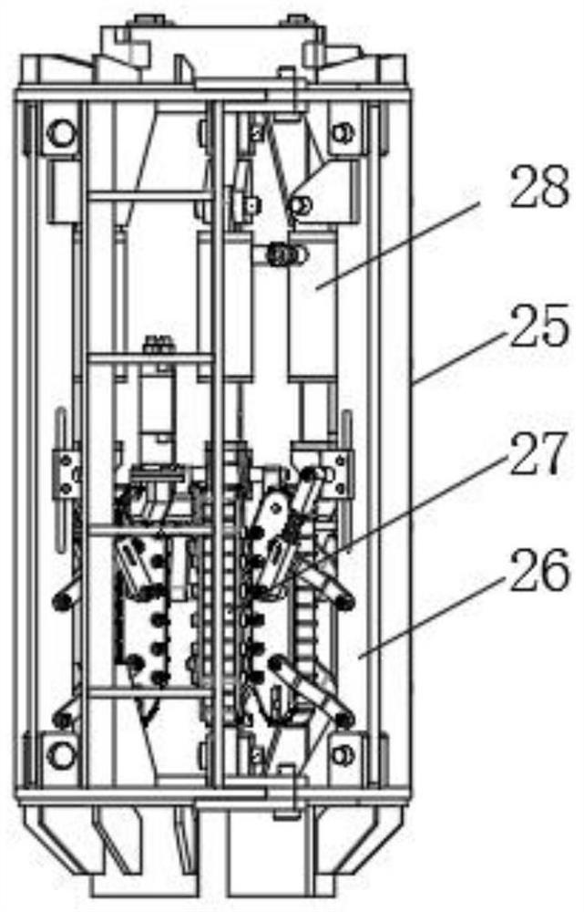
[0035] Such as Figure 1-6 As shown, a fully automatic water quality analyzer includes a housing 1, an analyzer main body 2 is fixedly installed on the inner wall of the upper side of the housing 1, and a lead screw seat 6 is also fixedly installed on the inner wall of the upper side of the housing 1, so that A moving seat 8 is mounted on the screw seat 6 to slide along the horizontal direction, and a lifting cylinder 9 is fixedly installed on the moving seat 8. The bottom end of the output rod of the lifting cylinder 9 is ...


PUM


Abstract

The invention discloses a full-automatic water quality analyzer and a working method thereof. The water quality analyzer comprises a shell, an analyzer main body is fixedly mounted on the inner wall of the upper side of the shell; a first air cylinder clamping jaw and a rotary air cylinder are fixedly mounted on an air cylinder mounting frame; a lifting mechanism is fixedly installed on the innerwall of the lower side of the shell and used for driving a sampling barrel to ascend and descend, a storage vessel is arranged on a supporting base, a second air cylinder clamping jaw is fixedly installed at the top of a connecting plate, a third air cylinder clamping jaw is fixedly installed at one end of a rotating rod, a funnel is installed on the inner wall of the lower side of the shell, anda liquid discharging pipe is fixedly installed at the bottom of the funnel. The water quality analyzer can float in water, manual lifting is not needed during sampling, the labor intensity is reduced,the water quality analyzer can automatically perform sampling, is convenient to carry, automatic in operation, convenient and rapid, can automatically pour out an analyzed sample, and ensures that the internal environment of the water quality analyzer is clean and tidy.

Description

technical field [0001] The invention relates to a water quality analyzer, in particular to a fully automatic water quality analyzer and a working method thereof. Background technique [0002] Human life and production water have specific requirements for water quality. Water used in different fields needs to meet different water quality standards. The monitoring of water in the natural environment mainly includes physical indicators, chemical indicators and microbial indicators. Water quality analyzers are mainly used in tap water. , surface water, sewage, ocean water, and other water quality analysis; traditional water quality analyzers require manual sampling, which is labor-intensive and not easy to carry. It also requires manual assistance during work, and the operation is cumbersome. It may cause the sample to be spilled inside the water quality analyzer, and the internal environment of the water quality analyzer cannot be guaranteed to be clean and tidy. Contents of ...

Claims


Application Information

Patent Timeline
IPC IPC(8): G01N33/18G01N1/10G01N35/00G01N35/10
CPCG01N33/18G01N1/10G01N35/0099G01N35/10
Inventor 贺喜双尹志斌顾俊清
Owner 安徽清大云博环保科技有限公司
Learn More