Microstrip antenna combination structure with coupling suppression function

A technology of microstrip antenna and combined structure, which is applied in the direction of separately energized antenna array, antenna, antenna coupling, etc., can solve the problems of small distance, equipment failure, and influence of aircraft platform electromagnetic compatibility, etc., and achieve small distance and simple structure Effect

Active Publication Date: 2020-11-24
BEIHANG UNIV
View PDF6 Cites 0 Cited by
  • Summary
  • Abstract
  • Description
  • Claims
  • Application Information

AI Technical Summary

Problems solved by technology

However, the antenna layout on traditional airborne platforms is designed with a certain degree of electromagnetic compatibility. If the antennas originally distributed throughout the fuselage are put together to work at the same time, the mutual isolation between the antennas and the electromagnetic compatibility of the system will Compatibility will be a prominent issue
In addition, since the antennas working in the same antenna aperture often have similar functions and similar operating frequencies, the mutual interference between the antennas will be very serious, which will have a huge impact on the electromagnetic compatibility of the entire aircraft platform. Otherwise, the performance of the device will be degraded, and if it is serious, it may cause the device to fail to work at all or receive wrong information, and even cause damage to the device.
[0003] The existing antenna coupling suppression method is to increase the distance between the antennas or set a single type of microstrip antenna or use the aircraft body as a shield, etc., but because the distance between the antennas in the same antenna aperture is extremely small, the above method is no longer necessary. Be applicable

Method used


Image

  • Microstrip antenna combination structure with coupling suppression function
  • Microstrip antenna combination structure with coupling suppression function
  • Microstrip antenna combination structure with coupling suppression function

Examples


Embodiment 1

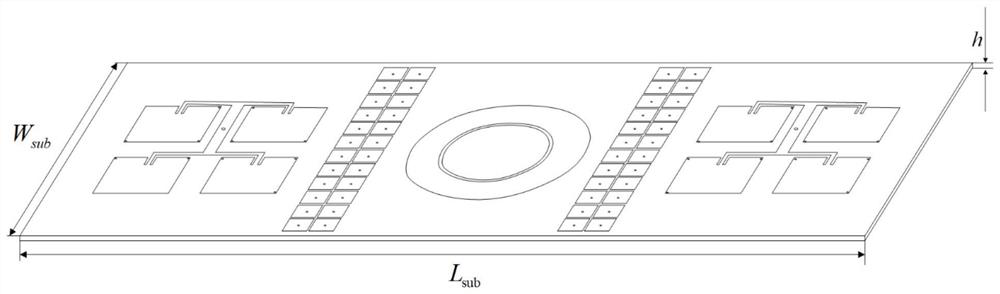
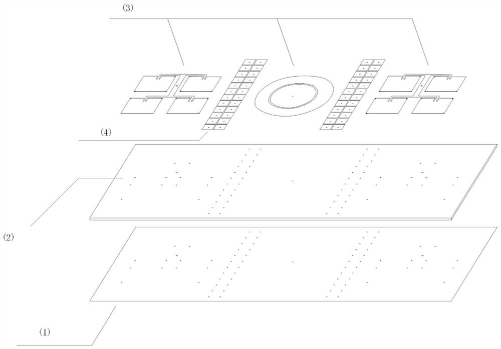
[0034] see Figure 1-3 As shown, a combined microstrip antenna structure with coupling suppression function, including the bottom layer, middle layer and upper layer, the bottom layer is a metal floor (1), the middle layer is a dielectric substrate (2), and the upper layer is a printed antenna radiation structure (3) , The printed metal floor (1) is provided with via holes and feeds power, and it is characterized in that the antenna radiation structure (3) includes a four-element rectangular microstrip antenna array and a circular microstrip antenna.

[0035] The upper layer also has an electromagnetic bandgap structure (4).

[0036] The antenna radiation structure (3) is made up of a four-element rectangular microstrip antenna array and an annular microstrip antenna. The power flow at the power point is divided into four parts to feed the array elements of the microstrip antenna respectively, and the circular loop antenna is composed of a circular patch and a circular patch ...

Embodiment 2

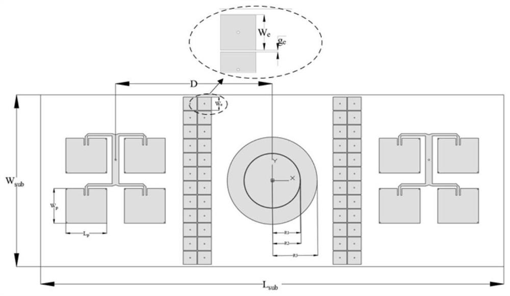
[0055] see Figure 6-7 As shown, its structural setting is the same as that in Embodiment 1, and particularly described antenna radiation structure (3) is made up of two four-element rectangular microstrip antenna arrays and a ring-shaped microstrip antenna

[0056] In embodiment 2, the size of above-mentioned each parameter is as follows:

[0057] W sub =80mm, L sub =170mm, h=2mm;

[0058] D=85mm;

[0059] R 1 =20.45mm,R 2 =20.8mm,R 3 =33mm;

[0060] W p =26.35mm,L p = 30mm.

[0061] like Figure 9 As shown, in this embodiment, the antenna S11 works around 4.3 GHz, and the antenna S22 works around 5.06 GHz.

[0062] like Figure 10 As shown, the coupling strength of the antenna S11 and the antenna S22 is -60.5dB at 5.06GHz, which is 20dB lower than the traditional microstrip antenna combination -40.5dB, and has a coupling suppression effect at the required frequency point.

[0063] In particular, the microstrip antenna structure of the present invention can be a...


PUM

PropertyMeasurementUnit
radiusaaaaaaaaaa
thicknessaaaaaaaaaa
wavelengthaaaaaaaaaa

Abstract

The invention discloses a microstrip antenna combination structure with a coupling inhibition function. The structure comprises a bottom layer, a middle layer and an upper layer, the bottom layer is aprinted metal floor, the middle layer is a dielectric substrate, the upper layer is a printed antenna radiation structure, the antenna is fed by a coaxial line, the printed metal floor is provided with a via hole and feeds, and the antenna radiation structure comprises a quaternary rectangular microstrip antenna array and an annular microstrip antenna. The structure can suppress coupling betweenmicrostrip antennas.

Description

technical field [0001] The invention relates to the technical field of antennas, in particular to a combined microstrip antenna structure with a coupling suppression function. Background technique [0002] In the advanced fighter avionics system, the antenna has changed from a discrete antenna to an aperture integrated antenna. However, the antenna layout on traditional airborne platforms is designed with a certain degree of electromagnetic compatibility. If the antennas originally distributed throughout the fuselage are put together to work at the same time, the mutual isolation between the antennas and the electromagnetic compatibility of the system will Compatibility will be a prominent issue. In addition, since the antennas working in the same antenna aperture often have similar functions and similar operating frequencies, the mutual interference between the antennas will be very serious, which will have a huge impact on the electromagnetic compatibility of the entire a...

Claims


Application Information

Patent Timeline
Patent Type & Authority Applications(China)
IPC IPC(8): H01Q1/38H01Q1/52H01Q21/06
CPCH01Q1/38H01Q1/523H01Q1/521H01Q21/061
Inventor 吴琦
Owner BEIHANG UNIV
Why Eureka
Try Eureka