
Radio frequency circuit and electronic equipment

A technology of radio frequency circuits and radio frequency signals, which is applied in the fields of electrical components, wireless communication, connection management, etc., and can solve the problems of high wiring loss of antennas and switch modules, etc.

Active Publication Date: 2020-11-20
VIVO MOBILE COMM CO LTD
View PDF3 Cites 15 Cited by
  • Summary
  • Abstract
  • Description
  • Claims
  • Application Information

AI Technical Summary

Problems solved by technology

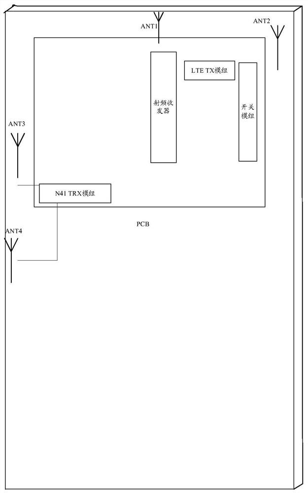
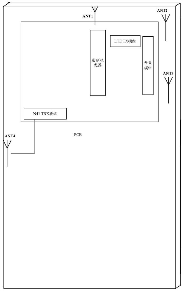
[0005] The purpose of the embodiment of the present application is to provide a radio frequency circuit and electronic equipment, which can solve the problem of large wiring loss between the antenna and the switch module used to transmit or receive N41 radio frequency signals in the existing antenna layout architecture

Method used


Image

  • Radio frequency circuit and electronic equipment
  • Radio frequency circuit and electronic equipment
  • Radio frequency circuit and electronic equipment

Examples


Embodiment Construction

[0022] The technical solutions in the embodiments of the present application will be clearly and completely described below in conjunction with the accompanying drawings in the embodiments of the present application. Obviously, the described embodiments are part of the embodiments of the present application, rather than all of them. Based on the embodiments in this application, all other embodiments obtained by those of ordinary skill in the art without creative work shall fall within the protection scope of this application.

[0023] The terms "first" and "second" in the specification and claims of this application are used to distinguish similar objects, but not to describe a specific sequence or sequence. It should be understood that the data used in this way can be interchanged under appropriate circumstances so that the embodiments of the present application can be implemented in a sequence other than those illustrated or described herein. In addition, "and / or" in the specif...


PUM


Abstract

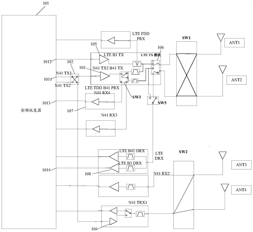
The invention discloses a radio frequency circuit and electronic equipment, and belongs to the technical field of communication, the radio frequency circuit comprises a radio frequency transceiver, afirst switch module, a first emission module, a second emission module, a second switch module and M antennas; the radio frequency transceiver comprises a first transmitting port; the input end of thefirst switch module is connected with the first transmitting port, and the two output ends of the first switch module are connected with the input end of the first transmitting module and the input end of the second transmitting module respectively; the output ends of the first transmitting module and the second transmitting module are respectively connected to the M antennas through the second switch module; the first transmitting port is conducted with the first transmitting module under the condition that the first switch module is in a first state, and the first transmitting port is conducted with the second transmitting module under the condition that the first switch module is in a second state; the first transmitting module is used for transmitting a first network type radio frequency signal and a second network type radio frequency signal, and the second transmitting module is used for transmitting a second network type radio frequency signal.

Description

Technical field [0001] This application belongs to the technical field of electronic equipment, and specifically relates to a radio frequency circuit and electronic equipment. Background technique [0002] For 5G terminals, in order to obtain a better user experience, they all have a multi-antenna switching function, namely Antenna Switch Diversity (ASDiv) function; but in a non-standalone (NSA) scenario, in order to meet Long Term Evolution (LTE) and New Radio (NR) frequency bands do not conflict with each other in the signal path configuration and antenna path configuration. The terminal adopts a 6-antenna solution design, such as Figure 5 Shown. Since the 6-antenna design scheme uses a large number of antennas and will occupy more space in the terminal, a 5-antenna scheme is designed in related technologies, such as Image 6 Shown. [0003] In the process of realizing this application, the inventor found at least the following problems in the prior art: [0004] The layout of th...

Claims


Application Information

Patent Timeline
Patent Type & Authority Applications(China)
IPC IPC(8): H04B1/401H04B1/00H04W76/28
CPCH04B1/401H04B1/0064H04B1/0057H04B1/006H04W76/28
Inventor 韦仁杰易伟
Owner VIVO MOBILE COMM CO LTD
Learn More