Sputum suction device for emergency department

A technology of emergency department and sputum suction tube, which is applied to the field of sputum suction devices in emergency department, can solve the problems of increased cost, laryngeal mucosal damage, difficulty in breathing of patients, etc., and achieves the effect of improving efficiency

Active Publication Date: 2020-11-17
THE FIRST AFFILIATED HOSPITAL OF HENAN UNIV OF SCI & TECH
View PDF6 Cites 2 Cited by
  • Summary
  • Abstract
  • Description
  • Claims
  • Application Information

AI Technical Summary

Problems solved by technology

[0002] For patients with a lot of sputum, it is necessary to suck out the sputum in time to prevent blockage of the respiratory tract, which will cause difficulty in breathing and even threaten the life of the patient
There are two kinds of existing sputum suction devices. One is a manual sputum suction device. When a patient encounters an emergency, the manual sputum suction device is difficult to quickly suck out the blocked sputum due to insufficient power. medical malpractice
The other is an automatic sputum suction device. For this type of sputum suction device, it can quickly suck out the blocked sputum. Sometimes it is difficult to suck out viscous sputum, and due to the strong power of sputum suction, it is easy to cause damage to the patient's throat mucosa, which increases the pain of the patient
[0003] In addition, the structure of some sputum suction devices is too complicated, which increases the cost and makes it difficult to move and use

Method used


Image

  • Sputum suction device for emergency department
  • Sputum suction device for emergency department
  • Sputum suction device for emergency department

Examples


Embodiment Construction

[0040] In order to make the object, technical solution and advantages of the present invention clearer, the present invention will be further described in detail below in conjunction with the accompanying drawings and embodiments. It should be understood that the specific embodiments described here are only used to explain the present invention, not to limit the present invention.

[0041] Based on the embodiments of the present invention, all other embodiments obtained by persons of ordinary skill in the art without creative efforts fall within the protection scope of the present invention.

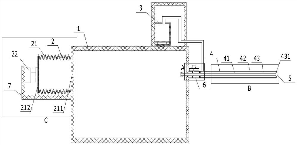
[0042] see figure 1 , which provides a structural schematic diagram of a sputum suction device for emergency department according to an embodiment of the present invention. The sputum suction device for the emergency department includes a sputum collection box 1 for collecting sputum; one side of the sputum collection box 1 is provided with a negative pressure mechanism 2 for forming a ...


PUM


Abstract

The invention provides a sputum suction device for an emergency department. The sputum suction device comprises a sputum collecting box, a negative pressure mechanism is arranged on one side of the sputum collecting box, a sputum suction tube is arranged on the other side of the sputum collecting box, and a spraying mechanism is arranged on the side, close to the sputum suction tube, of the top ofthe sputum collecting box; the sputum suction tube comprises an inner tube and an outer tube, one end of the inner tube is sleeved with a driving assembly and extends into the sputum collecting box,and an extensible suction head is arranged at the other end of the inner tube; the outer tube sleeves the outer side of the inner tube, and a spraying cavity is formed by the outer tube and the outerwall of the inner tube; a mist outlet of the spraying mechanism communicates with the spraying cavity; the driving assembly can drive the inner tube to move along the outer tube; and when separated from the outer tube, the extensible suction head is unfolded and connected with the end part of the outer tube. By means of the double-layer structure of the sputum suction tube, sputum suction by the inner tube and spraying by the outer tube are conducted synchronously, and sputum can be sucked out conveniently while viscous sputum is wetted. The sputum suction efficiency is improved by unfolding the extensible suction head.

Description

technical field [0001] The invention belongs to the technical field of medical devices, and in particular relates to a sputum suction device for emergency department. Background technique [0002] For patients with a lot of sputum, it is necessary to suck out the sputum in time to prevent blockage of the respiratory tract, thereby causing difficulty in breathing and even threatening the life of the patient. There are two kinds of existing sputum suction devices. One is a manual sputum suction device. When a patient encounters an emergency, the manual sputum suction device is difficult to quickly suck out the blocked sputum due to insufficient power. Can cause very influential medical malpractice. The other is an automatic sputum suction device. For this type of sputum suction device, it can quickly suck out the blocked sputum. Sometimes it is difficult to suck out viscous sputum, and because the power of sucking sputum is relatively large, it is easy to cause damage to the...

Claims


Application Information

Patent Timeline
IPC IPC(8): A61M1/00A61M31/00
CPCA61M1/0058A61M1/0023A61M31/00A61M2210/065A61M1/84A61M2210/005Y02A50/30
Inventor 崔旭凤黄丹丹
Owner THE FIRST AFFILIATED HOSPITAL OF HENAN UNIV OF SCI & TECH
Why Eureka
Try Eureka