
Battery protection system and battery system

A protection system and over-discharge protection circuit technology, applied in battery overcharge protection, battery over-discharge protection, battery circuit devices, etc., can solve problems affecting client experience, battery voltage drop, battery voltage drop, etc., to improve Experience the effect and avoid the effect of consuming current

Active Publication Date: 2021-01-01
SUZHOU XYSEMI ELECTRONICS TECH CO LTD
View PDF4 Cites 0 Cited by
  • Summary
  • Abstract
  • Description
  • Claims
  • Application Information

AI Technical Summary

Problems solved by technology

When the application system is in the standby state, the battery protection system in the battery system will consume current by itself, and the system load will also consume current, which will cause the battery voltage to drop, which will easily cause the battery voltage to drop to the over-discharge of the over-discharge protection circuit in the battery protection system. Below the protection voltage
When the battery system starts to use again, the battery system needs to be charged for a long time before it can be used normally, which affects the experience of the client
Especially in the application system of small-capacity batteries, the long-term self-consumption of the battery system and system load is particularly likely to cause the battery system to enter the over-discharge protection state. Charge

Method used


Image

  • Battery protection system and battery system
  • Battery protection system and battery system
  • Battery protection system and battery system

Examples


Embodiment Construction

[0034] The present invention will be further described in detail below in conjunction with the accompanying drawings and embodiments. It should be understood that the specific embodiments described here are only used to explain the present invention, but not to limit the present invention. In addition, it should be noted that, for the convenience of description, only some structures related to the present invention are shown in the drawings but not all structures.

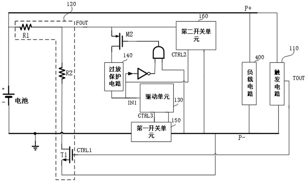
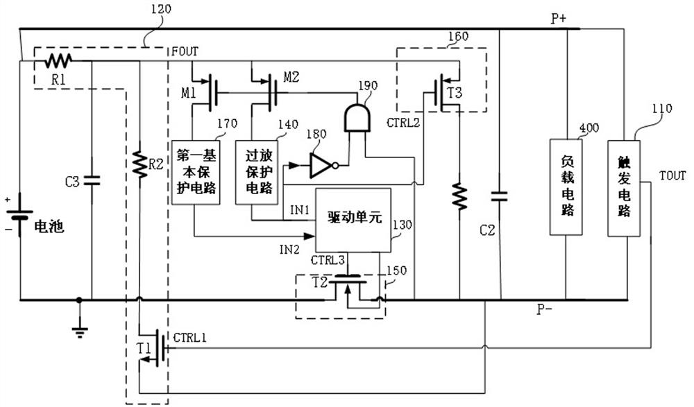
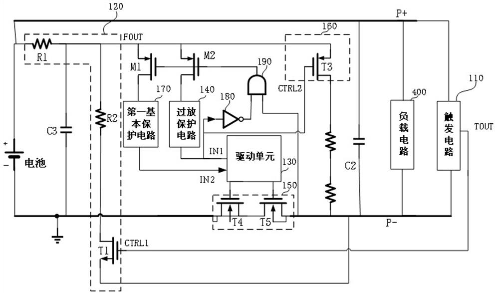
[0035] figure 1 It is a schematic structural diagram of a battery protection system provided by an embodiment of the present invention. Such as figure 1 As shown, the battery protection system includes a trigger circuit 110, a voltage division control circuit 120, a drive unit 130, an over-discharge protection circuit 140, a first switch unit 150 and a second switch unit 160; the trigger signal output terminal TOUT of the trigger circuit 110 and The control terminal CTRL1 of the voltage division control circuit ...


PUM


Abstract

The invention discloses a battery protection system and a battery system. The battery protection system comprises a trigger circuit and a voltage division control circuit. The trigger signal output end of the trigger circuit is connected with the control end of the voltage division control circuit and used for controlling the voltage division output end of the voltage division control circuit to output a voltage division signal when the trigger signal output end outputs a trigger signal. The voltage division output end of the voltage division control circuit is connected with the input end ofan over-discharge protection circuit; when the voltage division control circuit outputs a voltage division signal, the over-discharge protection circuit controls the first switch unit to be switched off and the second switch unit to be switched on, so that the over-discharge protection circuit is switched off, meanwhile, the battery protection system is in a completely switched-off state, the battery protection system and the load circuit are prevented from consuming current, and the battery voltage can be maintained at a stable voltage for a long time. When the battery protection system is started again for use, the battery protection system can be normally used only by activating the charger, and the battery does not need to be charged for a long time, so that the experience effect of the client is improved.

Description

technical field [0001] The embodiments of the present invention relate to the technical field of batteries, and in particular to a battery protection system and a battery system. Background technique [0002] The battery system can power the application system. For example, when the application system is a display device, the battery system supplies power to the display device. Current battery systems include batteries and battery protection systems. When the application system is in the standby state, the battery protection system in the battery system will consume current by itself, and the system load will also consume current, which will cause the battery voltage to drop, which will easily cause the battery voltage to drop to the over-discharge of the over-discharge protection circuit in the battery protection system. Below the protection voltage. When the battery system is started to use again, the battery system needs to be charged for a long time before it can be u...

Claims


Application Information

Patent Timeline
Patent Type & Authority Patents(China)
IPC IPC(8): H02J7/00H02H7/18
CPCH02H7/18H02J7/0029H02J7/00302H02J7/00306H02J7/0069
Inventor 蒋锦茂张以见
Owner SUZHOU XYSEMI ELECTRONICS TECH CO LTD
Learn More