
Linear output ventilator control method based on movable blade and rotating speed coupling adjustment

A speed coupling and control method technology, applied in the direction of pump control, machine/engine, mechanical equipment, etc., can solve the problems of wind pressure increase, decrease, and adverse effects on combustion stability in the furnace, so as to eliminate jumps, improve adjustment accuracy, The best overall performance of the equipment

Active Publication Date: 2020-11-06
XIAN THERMAL POWER RES INST CO LTD
View PDF2 Cites 2 Cited by
  • Summary
  • Abstract
  • Description
  • Claims
  • Application Information

AI Technical Summary

Problems solved by technology

But in another angle range, a small change in the installation angle of the moving blades can cause a large increase or decrease in the air volume and wind pressure at the fan outlet.
The above phenomenon is common in all power plants at present, which is the congenital defect of the equipment caused by the mechanical structure of the fan blades
The non-linear correlation between fan output and rotor blade angle has adverse effects on the stability of combustion in the furnace

Method used


Image

  • Linear output ventilator control method based on movable blade and rotating speed coupling adjustment
  • Linear output ventilator control method based on movable blade and rotating speed coupling adjustment
  • Linear output ventilator control method based on movable blade and rotating speed coupling adjustment

Examples


Embodiment Construction

[0023] The present invention is described in further detail below in conjunction with accompanying drawing:

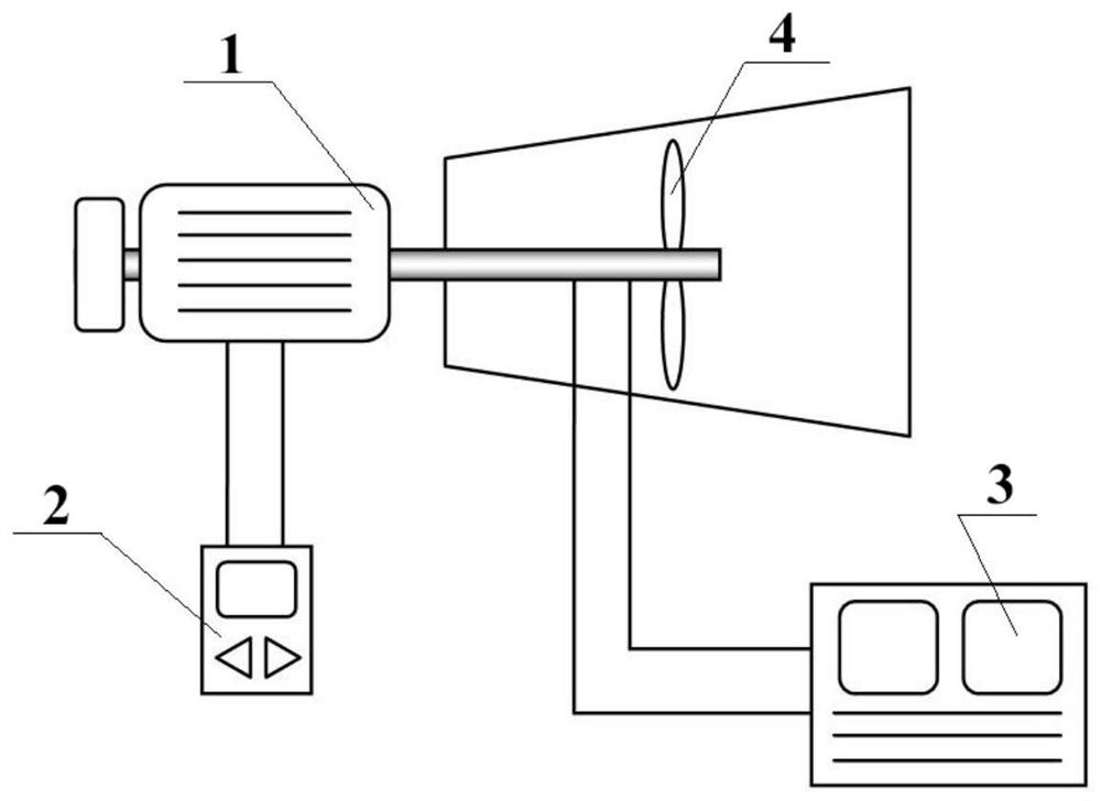
[0024] refer to image 3 According to the present invention, the linear output fan control method based on the rotor speed coupling adjustment includes the following steps:

[0025] 1) Select several typical working condition points, and obtain the parameters of each typical working condition point through experiments, wherein, the parameters of the typical working condition points include the current value of the motor 1, the fan speed and the angle of the moving blade 4, and establish the current value of the motor 1 The corresponding relationship between the value and the fan speed and the angle of the moving blade 4;

[0026] At a certain working condition point, the determined current value I of the motor 1 has a corresponding relationship with the fan speed P and the angle D of the moving blade 4. Therefore, the typical working condition point X can be used as I...


PUM


Abstract

The invention discloses a linear output ventilator control method based on movable blade and rotating speed coupling adjustment. The linear output ventilator control method comprises the following steps that a changing curve of the fan rotating speed along with a current value of a motor and a changing curve of the angle of movable blades along with the current value of the motor are fitted; and acurrent current value of the motor is obtained, according to the current current value of the motor, a given value of the fan rotating speed and a given value of the angle of the movable blades are obtained through the changing curve of the fan rotating speed along with the current value of the motor and the changing curve of the angle of the movable blades along with the current value of the motor which are obtained through fitting in the step 2, then the fan rotating speed and the angle of the movable blades are controlled according to the given value of the fan rotating speed and the givenvalue of the angle of the movable blades, and control over a linear output ventilator based on movable blade and rotating speed coupling adjustment is achieved. The method can improve the fan adjusting precision.

Description

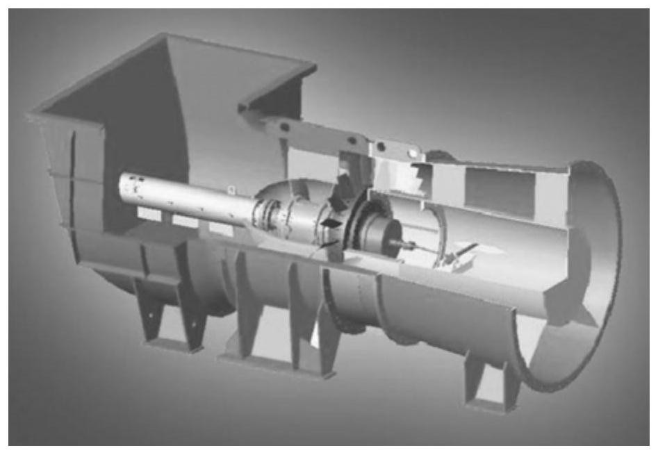
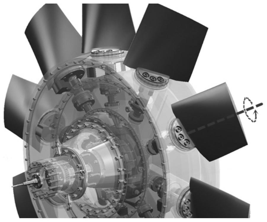
technical field [0001] The invention relates to a control method of a linear output fan, in particular to a control method of a linear output fan based on coupling adjustment of rotating blade rotation speed. Background technique [0002] At present, among the boiler auxiliary machines in thermal power plants, large fans such as blowers, induced draft fans, and primary fans mostly use axial flow fans with adjustable blades. The basic structure of this type of fans is as follows: figure 1 shown. Most of the driving motors of this type of fan use fixed-frequency ordinary motors, which means that the fan speed is a fixed value and cannot be adjusted. When the output of the fan needs to be adjusted, the matching hydraulic oil adjustment device is used to output power, so that each blade on the impeller rotates around the installation shaft, such as figure 2 As shown, the continuous change of the blade angle is realized, thereby changing the output of the fan. [0003] Becaus...

Claims


Application Information

Patent Timeline
Patent Type & Authority Applications(China)
IPC IPC(8): F04D27/00
CPCF04D27/007F04D27/004F04D27/002
Inventor 王林刘岗赵如宇伍刚高景辉孟颖琪
Owner XIAN THERMAL POWER RES INST CO LTD
Learn More