
Cardiologic interventional hemostat

A hemostatic device and cardiology technology, applied in the field of hemostatic devices, can solve the problems of reducing the wound healing speed, weakening the effect of the hemostatic device, and the direction of the cavity and the hemostatic head being not parallel, so as to improve the temperature of the drug and promote the activity. Effect

Active Publication Date: 2020-11-06
西安国际医学中心有限公司
View PDF7 Cites 2 Cited by
  • Summary
  • Abstract
  • Description
  • Claims
  • Application Information

AI Technical Summary

Problems solved by technology

The compression hemostatic device for cardiology department of the present invention includes a hemostatic head storage cabinet, a spare equipment storage bin and a built-in battery box. There is a pressure pump lifting switch on the top, a push piston in the medical pressure pump, a hemostatic head storage bin in the hemostatic head storage cabinet, a sterilant atomization box on the upper left side of the hemostatic head storage bin, and a sterilant atomization box There is an air dehumidification box on the right side, a lifting ring removal plate on the upper side of the electric hemostatic head, a protective gasket on the left side of the electric hemostatic head, a movable slider on the left side of the protective gasket, and a slider fixed on the movable slider Bolts; this technical solution is easy to use, easy to operate, time-saving and labor-saving, and reduces the work difficulty of medical staff when performing interventional therapy for wound hemostasis in the Department of Cardiology; however, this technical solution does not solve the cavity formed at the wound after the puncture is taken out The problem that it is not parallel to the pressing direction of the hemostatic head reduces the healing speed of the wound and weakens the effect of the hemostat

Method used


Image

  • Cardiologic interventional hemostat
  • Cardiologic interventional hemostat
  • Cardiologic interventional hemostat

Examples


Embodiment approach

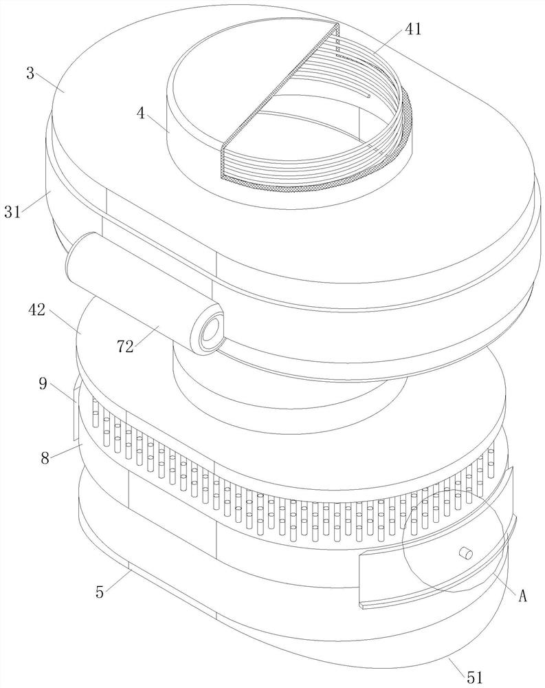
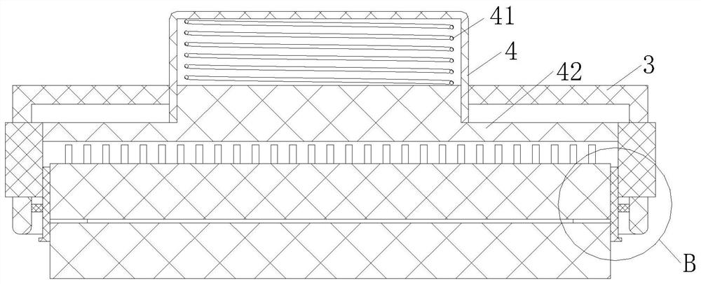
[0025] As an embodiment of the present invention, dense cilia 81 are arranged in the drug-smearing tablet 8, and the cilia 81 are slidably engaged in the drug-smearing tablet 8; The bottom of the through hole is located on the bottom port of the through hole; the knob 4 is in contact with the top of the cilia 81 during the descending process of operation; during the use of the hemostat, the composition in the tablet 8 is used to promote the healing of the wound, while Relying on the knob 4 of the hemostat to press the medicinal components into the patch 5, it is impossible to control the uniform transfer of the ingredients in the patch 8 to the patch 5, thereby reducing the promotion of wound healing; the present invention is set in The cilia 81 slide and engage in the tablet 8. When the operating knob 4 is lowered, the knob 4 touches the top of the cilia 81, making it move downward in the tablet 8, forming a uniform pattern on the lower surface of the tablet 8. and protrude i...


PUM


Abstract

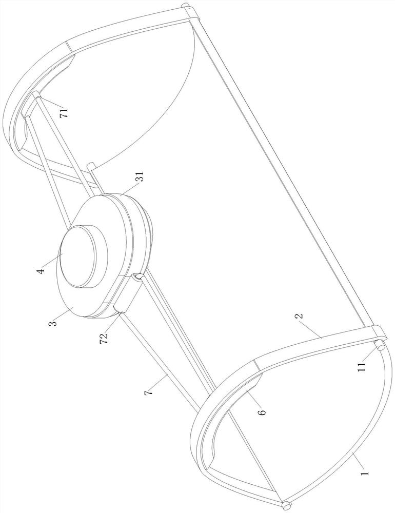
The invention relates to the technical field of hemostats, in particular to a cardiologic interventional hemostat. The cardiologic interventional hemostat comprises a bottom support, a locking band and a hemostatic block, wherein an application piece is arranged at the bottom of the hemostatic block; because the hemostat is compressed in a wound position before being puncture and taking out, a cavity formed in the surface of skin after the puncture and taking out ejects the application by operating a knob in the hemostatic block, the cavity after the puncture and taking out is in the axial direction of the base support, and the displacement of the compressed hemostatic block and the ejected application piece is in the radial direction of the bottom support, so that the healing effect on the wound is reduced, and the application effect of the hemostat is weakened. Therefore, an acting force for binding the hemostat is adjusted to the bottom support through a top support, the cavity caused in the axial direction of the bottom support in the wound after puncture and taking out is made up by use of rotation formed by arc-shaped bulges on the application piece in the hemostat, the contact effect of the hemostat on the wound compression is maintained, and the application effect of the cardiologic interventional hemostat is further enhanced.

Description

technical field [0001] The invention relates to the technical field of hemostats, in particular to an interventional hemostat in the Department of Cardiology. Background technique [0002] The Department of Cardiology, that is, the Department of Cardiovascular Medicine, often adopts interventional therapy in its medical process, and the therapeutic drug is sent to the cardiovascular lesion through puncture, which can exert the curative effect of the drug in a targeted manner and improve the efficiency of treatment; in the puncture therapy After completion, the puncture hole left in the skin wound is difficult to heal through the body's own hemostatic response, and an external hemostat is needed to meet the hemostatic purpose of the puncture wound. [0003] At present, most hemostats use the principle of compression to stop bleeding. By applying a certain pre-tightening pressure to the skin wound, the area of ​​the skin wound is reduced, and the blood flow at the part is slow...

Claims


Application Information

Patent Timeline
Patent Type & Authority Applications(China)
IPC IPC(8): A61B17/12A61M35/00
CPCA61B17/12A61B2017/12004A61M35/10
Inventor 杨艳妮杨秦陈青青
Owner 西安国际医学中心有限公司
Learn More