Planar transformers, power converters and circuit boards

A planar transformer and circuit board technology, applied in the direction of transformer/inductor coil/winding/connection, transformer/inductor components, circuits, etc., can solve the problem of difficulty in obtaining common mode current suppression effect, and achieve the best EMI performance , The effect of suppressing common mode current and reducing cost

Active Publication Date: 2022-04-01
SHENZHEN HUNTKEY ELECTRIC
View PDF3 Cites 0 Cited by
  • Summary
  • Abstract
  • Description
  • Claims
  • Application Information

AI Technical Summary

Problems solved by technology

However, the existing planar transformers are often difficult to obtain a good common-mode current suppression effect

Method used


Image

  • Planar transformers, power converters and circuit boards
  • Planar transformers, power converters and circuit boards
  • Planar transformers, power converters and circuit boards

Examples


Embodiment 1

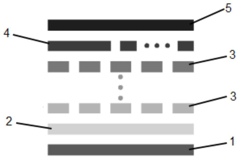
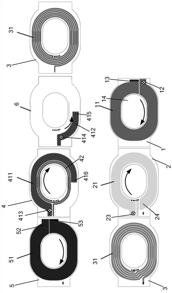
[0028] Such as figure 1 and 2 As shown, an embodiment of the planar transformer of the present invention is a secondary primary secondary structure, which includes a secondary coil layer 1, a shielding layer 2, and a plurality of primary coil layers 3 that are all located on the PCB board from bottom to top. , shielding layer 6, shielding layer 4 and secondary coil layer 5, the planar transformer is also provided with secondary static point end 12 and secondary moving point end 52, shielding layer 4 and shielding layer 6 are arranged on secondary coil layer 5 and primary Between the coil layers 3 , the shielding layer 2 is arranged between the secondary coil layer 1 and the primary coil layer 3 .

[0029] The secondary coil layer 1 includes the secondary coil 11, the secondary coil layer 5 includes the secondary coil 51, the shielding layer 2 includes the shielding coil 21, the shielding layer 4 includes a first shielding coil section 411 of N1 turns, and the shielding layer ...

Embodiment 2

[0040] Another preferred embodiment of the planar transformer of the present invention, it and figure 2 The embodiment is basically the same, the main differences include: the position of the shielding layer 2 is placed between the secondary coil layer 5 and the primary coil layer 3, and the shielding layer 4 and the shielding layer 6 are placed between the secondary coil layer 1 and the primary coil layer between 3.

[0041] In addition, the shielding layer 4 and the shielding layer 6 of this embodiment do not have an auxiliary coil, but the shielding layer 2 has an auxiliary coil.

[0042] The planar transformer designed by the present invention is suitable for an adapter or a charger whose output voltage is 5V-24V, or outputs a fixed voltage (5V / 12V / 15V / 19V / 20V / 24V) within this voltage range, or a variable voltage ( 5V-9V / 5V-11V / 5V-12V / 5V-15V / 5V-20V) power converter, adapter or charger.

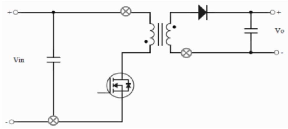
[0043] The present invention also provides a circuit board with a power conversion ...


PUM


Abstract

The invention provides a planar transformer, a power converter and a circuit board. The planar transformer includes a secondary coil layer on a PCB board, a shielding layer 1, a shielding layer 2 and a primary coil layer. The secondary coil layer includes at least part of A secondary coil, the secondary coil is provided with a secondary static point end; shielding layer one includes a first shielding coil segment of N1 turns, and the first shielding coil segment includes a first shielding static point end and a first shielding free end; shielding layer two The second shielding coil segment including N2 turns, the second shielding coil segment includes a second shielding static point end and a second shielding free end; the winding direction of the first shielding coil segment is the same as that of the secondary coil, and the first The winding direction of the shielding coil segment is opposite to the winding direction of the second shielding coil segment. The first shielding coil section of N1 turns and the second shielding coil section of N2 turns of the shielding coil of the present invention make both of them jointly play the role of suppressing the common mode current, and finally cooperate to make the sum of the common mode current very small.

Description

technical field [0001] The invention relates to the field of planar transformers, in particular to planar transformers, power converters and circuit boards. Background technique [0002] The common-mode current of the transformer has a great influence on EMI. It is necessary to reduce the common-mode current caused by the primary coil as much as possible. Usually, in a traditional transformer, the common-mode current is adjusted by adjusting the number of turns of the transformer shielding winding to reduce EMI. interference from common mode noise. [0003] Planar transformers are small in size and are more and more widely used in switching power supplies. However, it is often difficult to obtain a good common-mode current suppression effect in existing planar transformers. Contents of the invention [0004] The purpose of the present invention is to overcome the deficiencies of the prior art, and provide a planar transformer and a power converter to reduce the common-mo...

Claims


Application Information

Patent Timeline
Patent Type & Authority Patents(China)
IPC IPC(8): H01F27/28H01F27/38H02M3/335H02M1/44
CPCH01F27/2885H01F27/2804H01F27/38H02M3/33523H02M1/44H01F2027/2809H01F2027/2819
Inventor 肖民利
Owner SHENZHEN HUNTKEY ELECTRIC
Why Eureka
Try Eureka