
Path planning method and device based on ship angular velocity limitation

A technology of path planning and angular velocity, which is applied in the directions of measuring devices, instruments, surveying and navigation, etc., can solve the problems of ship instability and no consideration of ship angular velocity, etc., and achieve the effect of improving work efficiency

Inactive Publication Date: 2020-11-03
智慧航海(青岛)科技有限公司
View PDF5 Cites 0 Cited by
  • Summary
  • Abstract
  • Description
  • Claims
  • Application Information

AI Technical Summary

Problems solved by technology

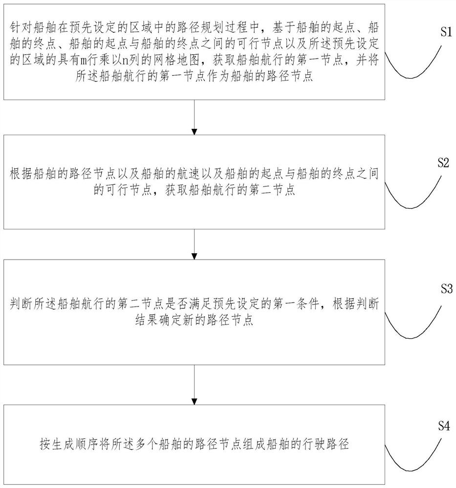
[0004] In view of the above-mentioned shortcomings and deficiencies of the prior art, the present invention provides a path planning method based on the limitation of the angular velocity of the ship, which solves the problem that the planned ship path in the prior art does not consider the angular velocity during the turning process of the ship, thus causing the ship to be unstable. technical issues

Method used


Image

  • Path planning method and device based on ship angular velocity limitation
  • Path planning method and device based on ship angular velocity limitation
  • Path planning method and device based on ship angular velocity limitation

Examples


Embodiment 1

[0065] This embodiment provides a path planning method based on ship angular velocity limitation, including:

[0066] S·0. According to the electronic chart of the preset area, obtain the feasible area and the unfeasible area of ​​the ship.

[0067] There are no obstacles in the feasible area.

[0068] There are obstacles in the infeasible area.

[0069] Preferably, said S.0 includes:

[0070] A rasterized map model of the preset area is established according to the electronic chart of the preset area.

[0071] The rasterized map model is read, a grid map with m rows multiplied by n columns is obtained, and a feasible area and an unfeasible area in the grid map are determined. The grid map has m×n grids.

[0072] S.1. Determine the starting point of the ship, the end point of the ship, and the feasible distance between the starting point and the end point of the ship according to the feasible area and the unfeasible area of ​​the ship, as well as the preset initial startin...

Embodiment 2

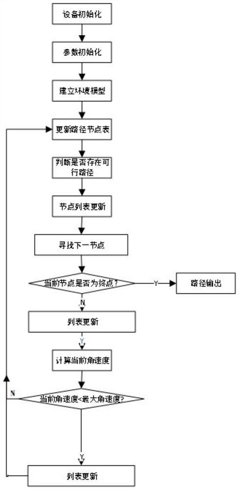
[0113] see figure 2 , a path planning method based on ship angular velocity limitation is adopted in the second embodiment, including:

[0114] In the preparatory stage of the second embodiment, a route planning method based on ship angular velocity limitation performs step S0 in advance, and obtains the feasible area and the unfeasible area of ​​the ship according to the electronic chart of the preset area.

[0115] There are no obstacles in the feasible area.

[0116] There are obstacles in the infeasible area.

[0117] Determine the starting point of the ship, the end point of the ship, and the feasible nodes between the starting point of the ship and the end point of the ship according to the feasible area and the unfeasible area of ​​the ship and the preset initial starting point and initial end point of the ship.

[0118] Wherein, step S0 specifically includes: step 1 to step 5.

[0119] Step 1: Device initialization.

[0120] Step 2: read in the electronic chart of...


PUM


Abstract

The invention relates to a path planning method based on ship angular velocity limitation, which comprises the following steps: in a path planning process of a ship in a preset area, based on a starting point of the ship, an end point of the ship, a feasible node between the starting point of the ship and the end point of the ship, and a grid map with m rows multiplied by n columns in the preset area, obtaining a first node of ship navigation, and taking the first node of ship navigation as a path node of a ship; obtaining a second node of ship navigation according to the path node of the ship, the navigation speed of the ship and the feasible node between the starting point of the ship and the end point of the ship; judging whether a second node of the ship navigation meets a preset firstcondition or not, and determining a new path node according to a judgment result; and forming the plurality of path nodes of the ship into a driving path of the ship according to a generation sequence.

Description

technical field [0001] The invention relates to the technical field of path planning, in particular to a path planning method and device based on ship angular velocity limitation. Background technique [0002] At present, the existing ship path planning algorithms are all planning based on position information, without considering the steering ability of the ship, and only plan the shortest path without collision from the starting port to the destination port. However, limited by the shape and maneuverability of the ship in practical applications, the minimum turning radius needs to be set for the turning of the ship during navigation. Therefore, the maximum angular rate of the ship during the turning process is limited. Moreover, the existing path planning algorithm is to smooth the path through Bezier curves, interpolation methods, and removal of invalid inflection points after obtaining the planned path, so as to avoid the situation of large steering angles as much as pos...

Claims


Application Information

Patent Timeline
Patent Type & Authority Applications(China)
IPC IPC(8): G01C21/20
CPCG01C21/203
Inventor 王晓原夏媛媛姜雨函高杰柴垒孙正濮朱慎超
Owner 智慧航海(青岛)科技有限公司
Learn More