
A rear-mounted rear-drive system for an electric vehicle

An electric vehicle and rear suspension technology, applied in the direction of electric power devices, power devices, control devices, etc., can solve the problems of difficult assembly and high cost, and achieve the effect of small assembly difficulty, low cost, and easy assembly

Active Publication Date: 2021-10-22
DONGFENG AUTOMOBILE COMPANY
View PDF10 Cites 2 Cited by
  • Summary
  • Abstract
  • Description
  • Claims
  • Application Information

AI Technical Summary

Problems solved by technology

[0004] The purpose of the present invention is to overcome the defects and problems of high cost and difficult assembly in the prior art, and provide a rear-mounted rear-drive system for electric vehicles with low cost and low assembly difficulty

Method used


Image

  • A rear-mounted rear-drive system for an electric vehicle
  • A rear-mounted rear-drive system for an electric vehicle
  • A rear-mounted rear-drive system for an electric vehicle

Examples


Embodiment 1

[0072] The present invention will be described in further detail below in conjunction with the accompanying drawings and specific embodiments.

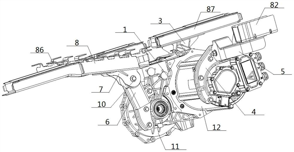
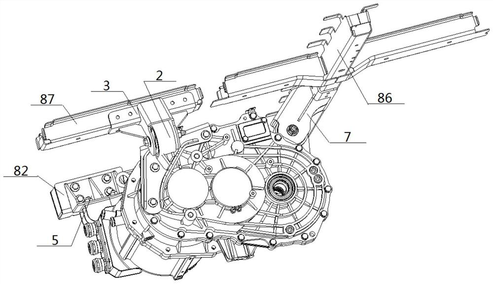
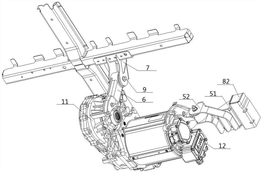
[0073] see figure 1 — Figure 18 , a rear rear drive system of an electric vehicle, comprising a power assembly 1 and a vehicle frame 8, the power assembly 1 includes a reduction box 11 and a drive motor 12, the right side of the front end of the reduction box 11 is connected to the drive motor 12 is connected to the left end, the two sides of the rear end of the reduction box 11 are respectively connected to the inner ends of the left drive shaft assembly 13 and the right drive shaft assembly 14, and the power assembly 1 is connected to the vehicle frame 8 through the suspension system ;

[0074] The suspension system includes a left suspension 2, a right suspension 4 and a rear suspension 6, the left side of the front end of the reduction box 11 is connected with the left suspension 2, and the junction of the left suspension 2 and...

Embodiment 2

[0078] Basic content is the same as embodiment 1, the difference is:

[0079] See Figure 19 , this figure is the pointed bolt 10 used when the present invention carries out the bolted connection, and it is also used as the pipe-through shaft 9 simultaneously. The pointed bolt 10 comprises a nut 101, a screw section 102, a threaded section 103, and a bolt head 104 connected in sequence, and the side wall of the threaded section 103 is provided with external threads, and the top of the bolt head 104 is connected to the threaded section. 103, the bottom end of the bolt head 104 extends outwards, and the diameter of the bolt head 104 is tapered from top to bottom.


PUM


Abstract

A rear-mounted rear-drive system for an electric vehicle, comprising a power assembly and a vehicle frame connected via a suspension system, the power assembly includes a reduction box and a drive motor, and the suspension system includes a left suspension, a right suspension The left side of the front end of the reduction box is connected to the left suspension, the connection between the left suspension and the reduction box is set opposite to the connection between the drive motor and the reduction box, and the right end of the drive motor is connected to the right suspension. Connection, the rear end of the reduction box is connected with the rear suspension near the joint of the reduction box and the right drive shaft assembly; the tops of the left suspension, right suspension and rear suspension are respectively provided with left shock absorbing module, right shock absorbing module, and rear shock absorbing module, the left, right, and rear shock absorbing modules are respectively connected to the vehicle frame through the corresponding left connecting unit, right connecting unit, and rear connecting unit, and the connecting units are all Tailored weldments made of plates. This design not only has lower cost and better vibration damping effect, but also has less difficulty in assembly and higher assembly efficiency.

Description

technical field [0001] The invention relates to a suspension technology of an electric vehicle, belongs to the field of pure electric vehicles and components of the pure electric vehicle, and in particular relates to a rear-mounted rear-drive system of the electric vehicle. Background technique [0002] According to the needs of the drive form, the layout of the powertrain is often arranged in the front cabin and the cockpit, and these two layouts have the form of front-mounted front-drive and rear-mounted rear-drive respectively. For the front-wheel drive, the suspension layout space, structural requirements and installation process requirements of the powertrain are not high, and it is easy to realize, but the rear-mounted rear drive, that is, when the powertrain is arranged at the rear axle of the vehicle, especially pure For electric van transport vehicles, the powertrain is completely under the floor, and the installation space is limited. When the mushroom-shaped cushi...

Claims


Application Information

Patent Timeline
Patent Type & Authority Patents(China)
IPC IPC(8): B60K1/00B60K17/06B62D21/02B62D21/11
CPCB60K1/00B60K17/06B62D21/02B62D21/11
Inventor 秦三元赵健生王为才郑兆刚张亮彭建斌肖恩禹明忠王浩宇
Owner DONGFENG AUTOMOBILE COMPANY
Learn More