An infusion device for neurosurgery care
An infusion device and neurosurgery technology, applied in the field of infusion, can solve the problems of unfavorable infusion, laborious, and the place where the infusion is not well fixed, etc.
- Summary
- Abstract
- Description
- Claims
- Application Information
AI Technical Summary
Problems solved by technology
Method used
Image
Examples
Embodiment 1
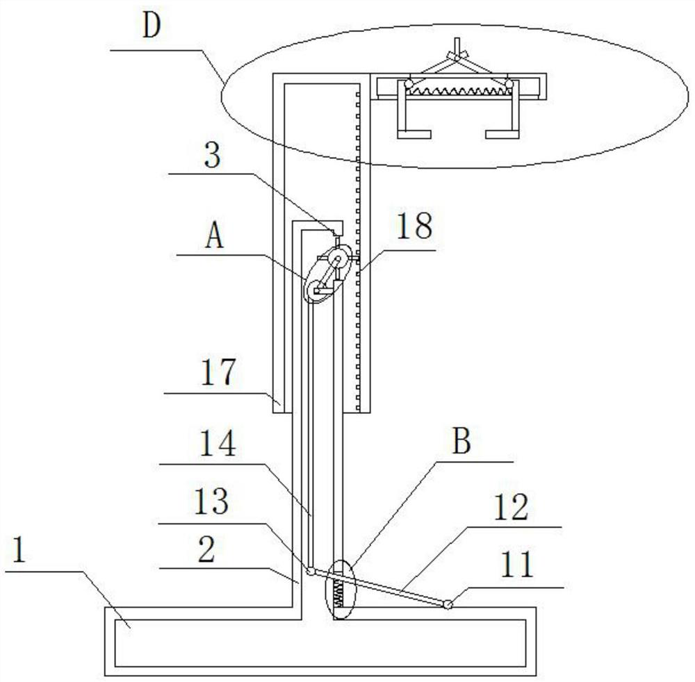
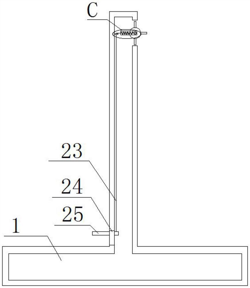
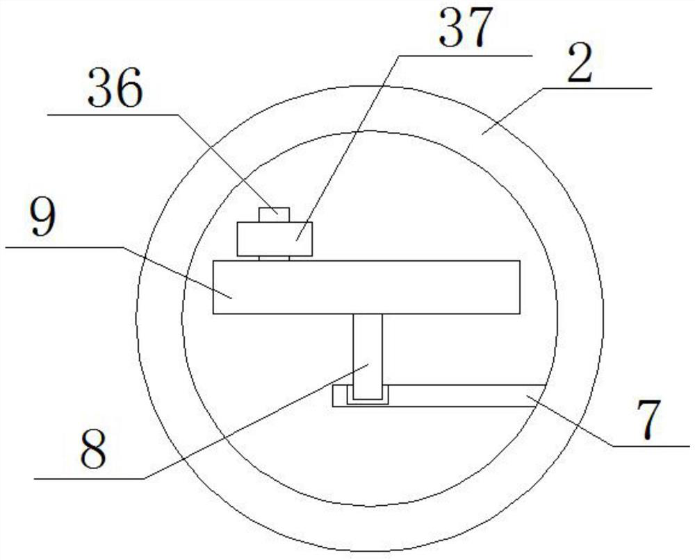
[0030] refer to Figure 1-8 , an infusion device for neurosurgery care, comprising a base 1, a vertical rod 2 is fixedly installed on the top of the base 1, the vertical rod 2 is a hollow structure, and the top of one side of the vertical rod 2 is provided with a first through hole 3, the first through hole 3 The first rotating shaft 4 is installed on the top, and the first rotating shaft 4 is fixedly sleeved with the first runner 5. The first runner 5 is evenly fixed and fixed with a plurality of limit blocks 6 around the ring. The vertical rod 2 is close to the first through hole. A support 7 is fixedly installed on the lower inner wall of the first through hole 3 on one side of the 3, and one end of the rotating rod 8 is rotated on the support 7, and the other end of the rotating rod 8 is fixedly installed with the second runner 9, the first rotating shaft 4 The upper is fixedly sleeved with a driven wheel, the rotating rod 8 is fixedly sleeved with a driving wheel, the dri...
Embodiment 2
[0032] In the present invention, a second through hole 15 is opened at the bottom of the vertical bar 2 near the first through hole 3 , and a second rotating shaft 11 is installed on the top of the base 1 near the second through hole 15 for rotation. On the second rotating shaft 11 One end of the pedal 12 is fixedly installed, and the other end of the pedal 12 extends into the vertical rod 2 through the second through hole 15, and the bottom of the pedal 12 is fixed on the inner wall of the bottom of the second through hole 15, which has the same second spring 16 , the second shaft 11 is used for rotation.
[0033] In the present invention, the other end of the pedal 12 extending into the vertical rod 2 is rotatably installed with a third rotating shaft 13 .
[0034] In the present invention, a short rod 36 is fixedly installed at a position far away from the center of the circle on the side of the second runner 9 away from the rotating rod 8 , and a rotating ring 37 is sleeve...
Embodiment 3
[0039] An infusion device for neurosurgical nursing, comprising a base 1, a vertical rod 2 is fixedly welded on the top of the base 1, the vertical rod 2 is a hollow structure, a first through hole 3 is chiseled on the top of one side of the vertical rod 2, and a first through hole 3 is formed on the top of the first through hole 3 The first rotating shaft 4 is installed in rotation, and the first rotating wheel 5 is fixedly sleeved on the first rotating shaft 4, and a plurality of limit blocks 6 are evenly fixed and welded around the first rotating wheel 5, and the vertical rod 2 is close to the first through hole 3 A bracket 7 is fixedly welded on the lower inner wall of the first through hole 3 on one side of the bracket 7, and one end of a rotating rod 8 is rotated on the bracket 7, and the other end of the rotating rod 8 is fixedly welded with a second runner 9, and on the first rotating shaft 4 The driven wheel is fixedly socketed, the driving wheel is fixedly socketed on...
PUM
 Abstract
Description
Claims
Application Information
 - R&D
- Intellectual Property
- Life Sciences
- Materials
- Tech Scout
- Unparalleled Data Quality
- Higher Quality Content
- 60% Fewer Hallucinations
Browse by: Latest US Patents, China's latest patents, Technical Efficacy Thesaurus, Application Domain, Technology Topic, Popular Technical Reports.
© 2025 PatSnap. All rights reserved.Legal|Privacy policy|Modern Slavery Act Transparency Statement|Sitemap|About US| Contact US: help@patsnap.com


