
Separating unit having an impaction surface

A technology of separation unit and impact surface, applied in the field of separation stage

Pending Publication Date: 2020-10-27
DUERR SYST GMBH
View PDF1 Cites 5 Cited by
  • Summary
  • Abstract
  • Description
  • Claims
  • Application Information

AI Technical Summary

Problems solved by technology

Due to the limited separation efficiency of the known inertial separators, an additional downstream filter is usually used for a finely cleaned gas flow

Method used


Image

  • Separating unit having an impaction surface
  • Separating unit having an impaction surface
  • Separating unit having an impaction surface

Examples


Embodiment Construction

[0135] In the figures, identical or identically acting parts are identified with the same reference numerals. The drawings show only embodiments and are not to be construed as limiting.

[0136] The directional terms used hereinafter with concepts such as "left", "right", "upper", "lower", "front", "rear", "rear" are only for better understanding of the drawings, and In no way is any limitation of generality indicated. The parts and elements shown and their design and use may vary at the discretion of those skilled in the art and may be adapted to the respective application.

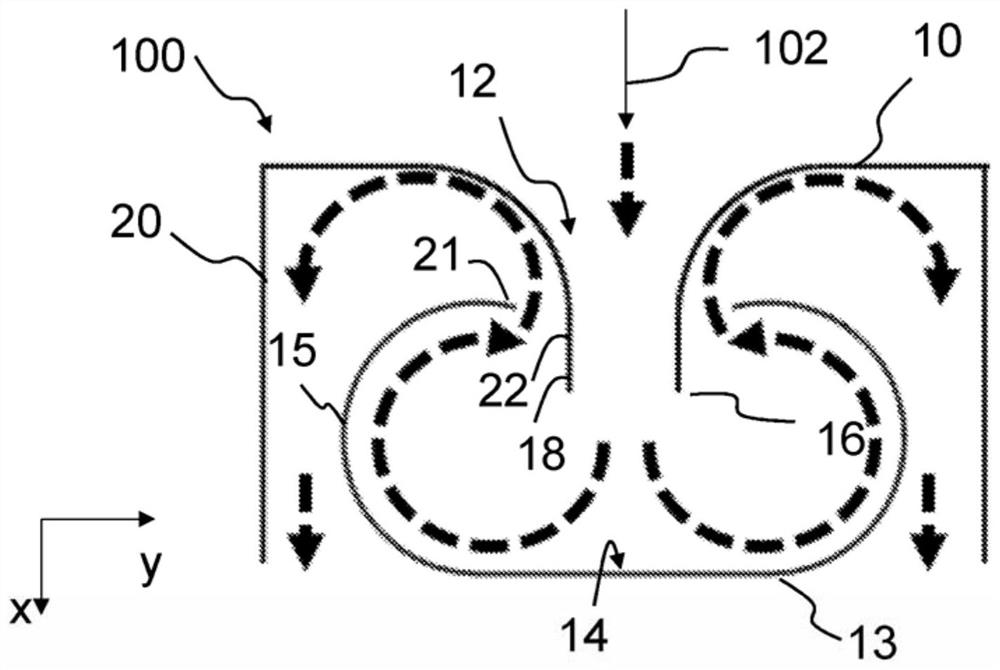
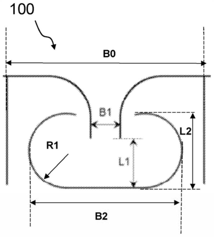
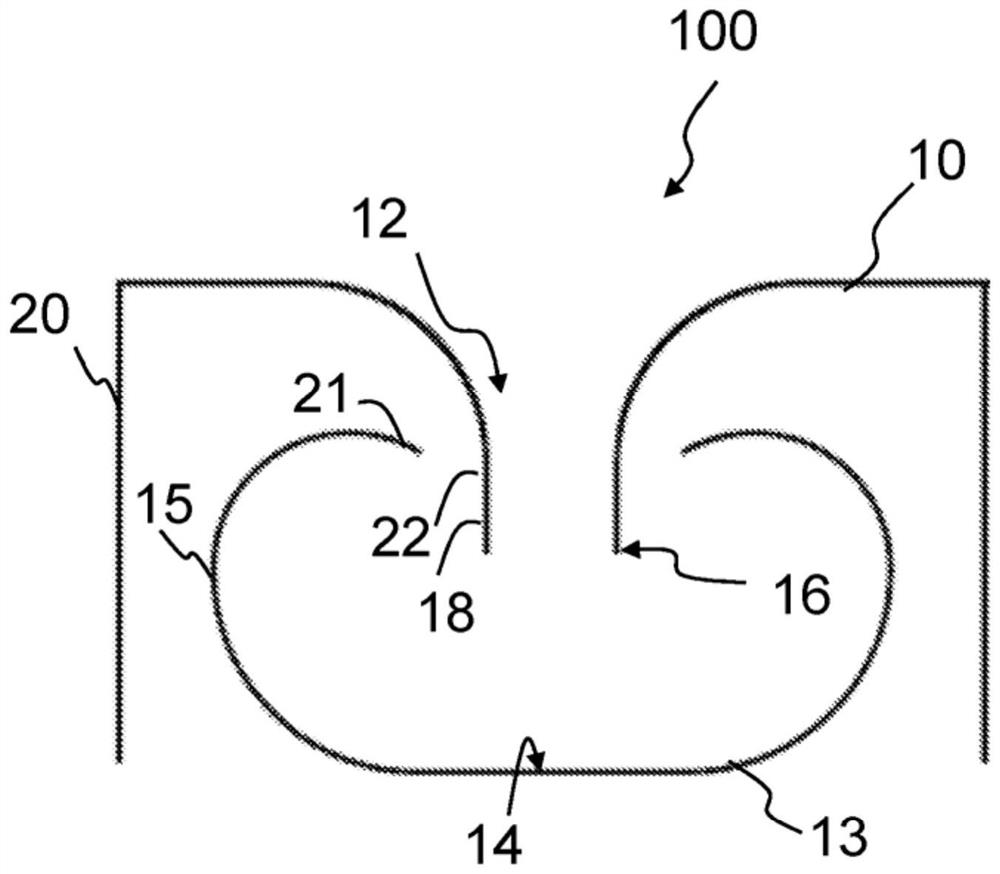
[0137] figure 1 shows a cross-sectional view through a separation stage 100 according to an embodiment of the invention, and figure 2 shows the basis figure 1 A cross-sectional view of the separation stage 100, which notes only the figure 1 The various characteristic parameters of the elements of the separation stage 100 are indicated with reference numerals in .

[0138] The separation stage 100 ...


PUM


Abstract

The invention relates to a separating stage (100) for the removal, by inertial impaction, of components, in particular paint particles and / or paint agglomerates, contained in a fluid flowing through.At least one separating segment is provided, which has, on the inlet side, at least one acceleration segment (12) for the fluid, in which the fluid is accelerated in a through-flow direction (102), and a first impaction surface (13) for components contained in the fluid is arranged downstream of the acceleration segment (12). The invention further relates to a separating unit (200) having at leastone separating stage (100), to a kit, to a transport cart, to a coating system, and to a method for producing a separating unit (200).

Description

technical field [0001] The invention relates to a separation stage for the inertial separation of components contained in a passing fluid, in particular paint particles and / or paint aggregates, and to a separation unit comprising at least one such separation stage. Background technique [0002] Inertial separators for separating dust particles or liquid droplets from gas streams are well known. Inertial separators are usually constructed from a number of very simply shaped flow bodies, such as tube semi-monocoques or trapezoidally bent plates, which are arranged in the gas flow such that they form a flow labyrinth. [0003] There are also various inertial separators on the market, which are specially designed to separate paint overspray from the exhaust or return air of painting plants. Here, it is usually meant to be a disposable separating unit, which is constructed, for example, from cardboard or plastic and which is disposed of as a whole once it has been fully loaded w...

Claims


Application Information

Patent Timeline
Patent Type & Authority Applications(China)
IPC IPC(8): B01D45/08B01D45/16B05B14/43
CPCB01D45/08B01D45/16B05B14/43B05B14/44B05B16/40B01D45/06Y02P70/10
Inventor 奥利弗·赛博特安德烈亚斯·诺伊
Owner DUERR SYST GMBH
Learn More