
A Particle Velocity Sensor with Wide Response Band

A particle vibration velocity and sensor technology, which is applied in the direction of instruments, measuring devices, and electrical devices, can solve problems such as wide response frequency band, response frequency band, sensitivity, signal-to-noise ratio, and signal distortion. Band response, to achieve the effect of frequency band response

Active Publication Date: 2022-06-28
THE THIRD RES INST OF CHINA ELECTRONICS TECH GRP CORP
View PDF13 Cites 0 Cited by
  • Summary
  • Abstract
  • Description
  • Claims
  • Application Information

AI Technical Summary

Problems solved by technology

However, the performance characteristics of this type of particle vibration sensor, such as response frequency band, sensitivity, and signal-to-noise ratio, are limited by various factors such as the structural size of the thermal resistance wire, the spacing of the thermal resistance wire, and the material selected for the sensor.
Therefore, the current particle velocity sensor is difficult to achieve a wide response frequency band under the premise of ensuring the signal-to-noise ratio and sensitivity in the frequency band
This will cause a series of problems such as signal distortion and large noise in the frequency band when the sensor detects broadband sound signals
This defect directly affects the detection of broadband sound signals by the particle velocity sensor, which limits the application scenarios and scope of application of the particle velocity sensor

Method used


Image

  • A Particle Velocity Sensor with Wide Response Band
  • A Particle Velocity Sensor with Wide Response Band
  • A Particle Velocity Sensor with Wide Response Band

Examples


Embodiment 1

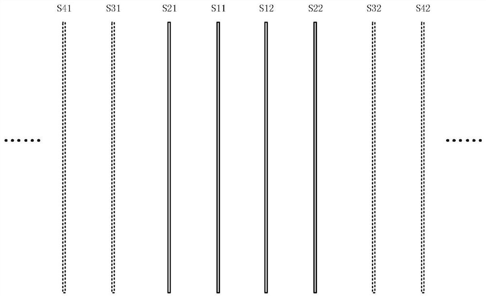
[0029] like figure 1 As shown, the sensor includes a sensing unit and a signal conditioning unit. The sensitive unit is composed of a plurality of sensitive sub-units, and each sensitive sub-unit is used to collect the sound signal of the corresponding frequency band; it includes a signal conditioning unit, and the signal conditioning unit is used to amplify the electrical signal output by the sensitive unit, and to The electrical signals output by each sensitive subunit are synthesized.

[0030] like figure 2 As shown, each sensitive subunit is composed of two parallel sensitive wires, and the sensitive unit includes a central sensitive subunit and one or more outer sensitive subunits. In this embodiment, the central sensitive subunit The unit is composed of sensitive wires S11 and S12, and also includes an outer sensitive subunit composed of sensitive wires S21 and S22, an outer sensitive subunit composed of sensitive wires S31 and S32, and an outer sensitive subunit comp...

Embodiment 2

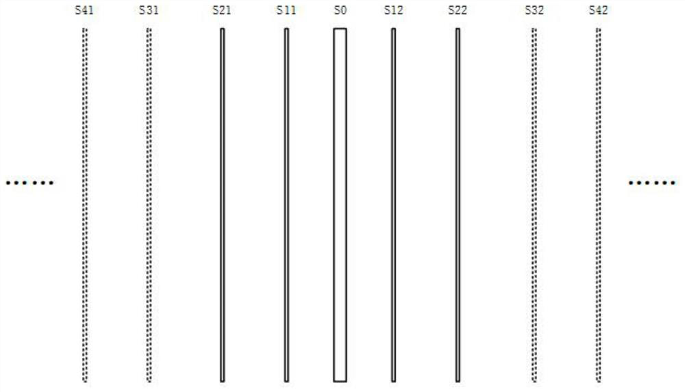
[0035] like image 3 As shown, a heating wire S0 is provided in the middle position between the sensitive wires S11 and S12 of the central sensitive subunit, and the response effect of the sensitive unit can be further improved by heating the wire S0.

[0036] The remaining structures and working principles of the second embodiment are the same as those of the first embodiment.


PUM


Abstract

The invention relates to a particle vibration velocity sensor with a wide response frequency band, which includes a sensitive unit, the sensitive unit is composed of a plurality of sensitive subunits, and each sensitive subunit is used to collect sound signals of corresponding frequency bands; it includes a signal conditioning unit, the The signal conditioning unit is used for amplifying the electrical signal output by the sensitive unit, and synthesizing the electrical signal output by each sensitive sub-unit. The invention can realize broadband response under the premise of ensuring signal-to-noise ratio and sensitivity.

Description

technical field [0001] The invention relates to a mass point vibration velocity sensor with a wide response frequency band. Background technique [0002] The acoustic signal contains two parameter values, the scalar sound pressure signal and the vector particle vibration velocity signal, which respectively reflect the different characteristics of the sound field. Source location tracking, sound field imaging and other aspects have broad application prospects in aeroacoustics, hydroacoustics and other fields. For the scalar sound pressure signal, it can be measured by a variety of sensors such as electret condenser microphones. For the sound vector signal, the traditional measurement method is generally based on the principle of sound pressure gradient for indirect measurement, that is, the gradient calculation is performed by the sound pressure detected by two microphones at a certain distance, so as to obtain the particle vibration velocity signal. [0003] The prior art ...

Claims


Application Information

Patent Timeline
Patent Type & Authority Patents(China)
IPC IPC(8): G01H11/06
CPCG01H11/06
Inventor 谢奕周瑜魏晓村冯杰刘云飞
Owner THE THIRD RES INST OF CHINA ELECTRONICS TECH GRP CORP
Learn More