
A control method of kitchen air conditioner

A control method and technology for kitchens, applied in the direction of control input involving air characteristics, space heating and ventilation control input, heating and ventilation control systems, etc., can solve problems such as insufficient conversion, energy waste, and supercooling, and avoid The local area is too cold and the user experience is good

Active Publication Date: 2022-04-05
VATTI CORP LTD
View PDF19 Cites 0 Cited by
  • Summary
  • Abstract
  • Description
  • Claims
  • Application Information

AI Technical Summary

Problems solved by technology

When the existing kitchen air conditioner is working, the air flow rate of the kitchen air conditioner is inconsistent, and it often does not work within the range of wind speed that the user feels comfortable. The refrigeration energy generated by the air conditioner cannot be fully converted, so that the kitchen air conditioner cannot work at its optimal efficiency, resulting in a waste of energy

Method used


Image

  • A control method of kitchen air conditioner
  • A control method of kitchen air conditioner

Examples


Embodiment 1

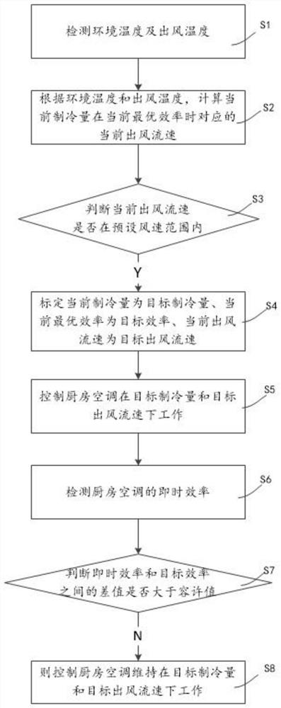
[0034] See attached figure 1 A control method of a kitchen air conditioner according to the present invention includes the following steps:

[0035] Step S1: Detect the ambient temperature and the air outlet temperature;

[0036] Step S2: According to the ambient temperature and the outlet air temperature, calculate the current outlet air flow rate corresponding to the current cooling capacity at the current optimal efficiency;

[0037] Step S3: judging whether the current air flow speed is within the preset wind speed range;

[0038] Step S4: If the current air flow speed is within the preset wind speed range, calibrate the current cooling capacity as the target cooling capacity, and the current air flow speed as the target air flow speed; if the current air flow speed is not within the preset wind speed range, calculate the next The next air flow rate corresponding to the cooling capacity at the next optimal efficiency;

[0039] Step S5: Control the kitchen air conditione...

Embodiment 2

[0052] see figure 2 It shows a control method of a kitchen air conditioner, the difference from Embodiment 1 is that after S5 controls the kitchen air conditioner to work under the target cooling capacity and the target air outlet flow rate, the following steps are further included:

[0053] Step S6: Calibrate the current optimal efficiency as the target efficiency;

[0054] Step S7: Obtain the instant efficiency of the kitchen air conditioner;

[0055] Step S8: judging whether the difference between the immediate efficiency and the target efficiency is greater than the allowable value;

[0056] Step S9: If the difference between the immediate efficiency and the target efficiency is less than the allowable value, control the kitchen air conditioner to maintain the target cooling capacity and the target air flow rate; if the difference between the immediate efficiency and the target efficiency is greater than the allowable value, Then adjust the current air flow rate.

[00...


PUM


Abstract

The present invention proposes a control method for a kitchen air conditioner, comprising the following steps: detecting the ambient temperature and the outlet air temperature; calculating the current outlet air flow rate corresponding to the current cooling capacity at the current optimal efficiency according to the ambient temperature and the outlet air temperature; judging Whether the current air flow rate is within the preset wind speed range; if the current air flow speed is within the preset wind speed range, the current cooling capacity is calibrated as the target cooling capacity, and the current air flow rate is the target air flow rate; if the current air flow rate is not Within the preset wind speed range, calculate the next air flow rate corresponding to the next cooling capacity at the next optimal efficiency; control the kitchen air conditioner to work under the target cooling capacity and target air flow rate. Controlling the outlet air velocity within the preset air velocity range enables the user to cook food in a comfortable air velocity environment.

Description

technical field [0001] The invention relates to the technical field of kitchen appliances, in particular to a control method for a kitchen air conditioner. Background technique [0002] With the continuous improvement of living standards, people's requirements for the comfort of the kitchen environment are also increasing. In the cooking process, not only will a large amount of oil fume be generated, especially in summer when the stove is used, a large amount of heat radiation will be generated, which will make the user uncomfortable and cause the user During the cooking process, the experience is poor. [0003] The kitchen air conditioner includes an air conditioner that sucks in indoor air and discharges it after exchanging heat, a fume exhaust hood that discharges the heat and odor generated during cooking to the outside, and guides and discharges the air that has been heat exchanged and discharged by the air conditioner to the smoke exhaust. A guide device under the out...

Claims


Application Information

Patent Timeline
Patent Type & Authority Patents(China)
IPC IPC(8): F24F11/64F24F11/89F24F110/10F24F110/30
CPCF24F11/64F24F11/89F24F2110/10F24F2110/30
Inventor 麦伟添陈权明许胜涛潘叶江
Owner VATTI CORP LTD
Learn More