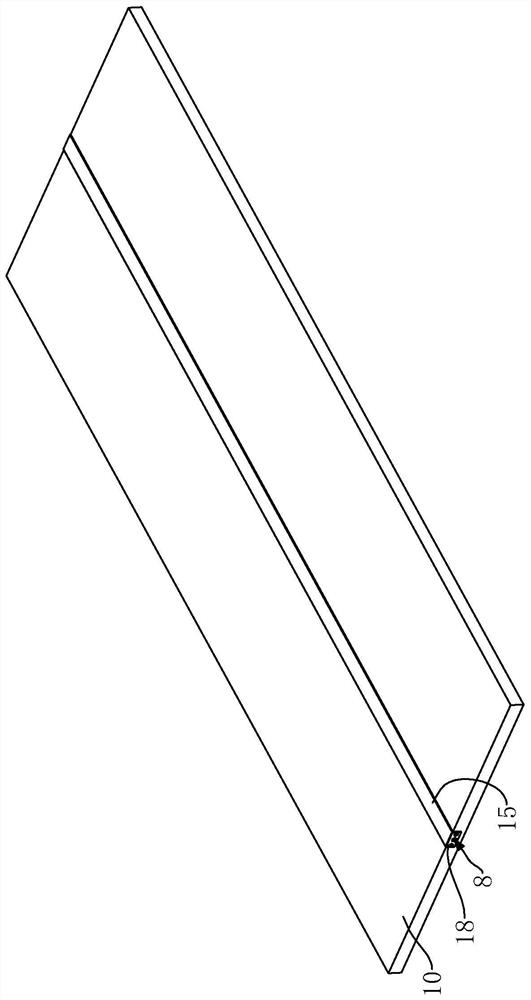
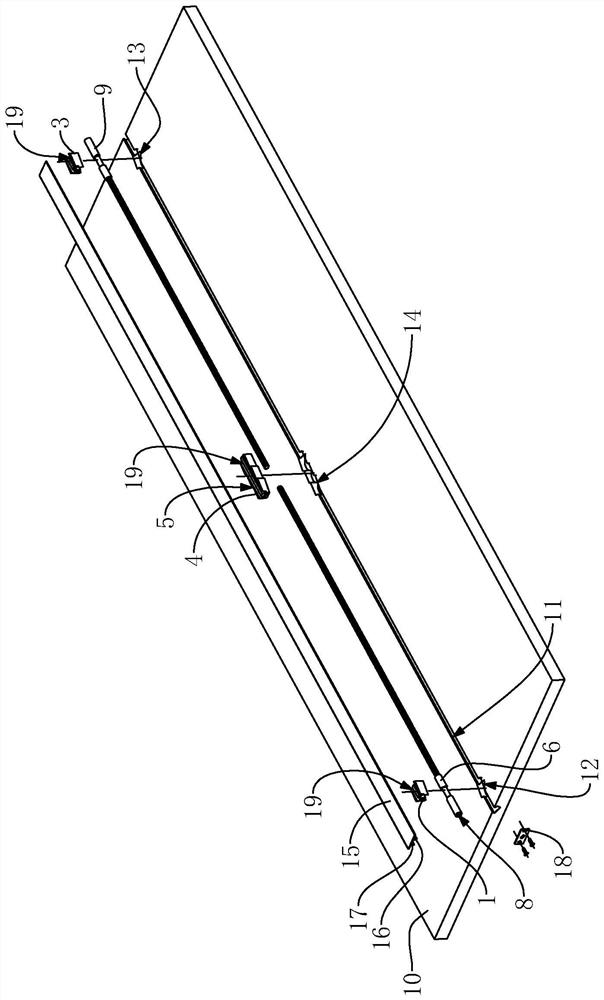
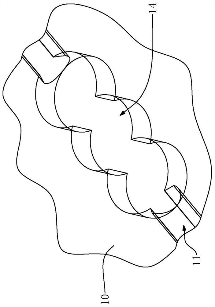
Straightening device, door plate and cabinet

A technology for door panels and sealing panels, applied in the field of door panels, cabinets, and straightening devices, can solve the problems of inability to correct door panels, small straightening amount, and poor generality of straightening devices.

Pending Publication Date: 2020-10-27
SUOFEIYA HOME COLLECTION
View PDF0 Cites 0 Cited by
  • Summary
  • Abstract
  • Description
  • Claims
  • Application Information

AI Technical Summary

Problems solved by technology

[0003] In the prior art, there are usually two straightening methods for the straightening device: 1. The straightening device drives the deformation of the door panel through its own deformation to achieve the correction effect. This straightening method can make the appearance of the door panel beautiful, but the amount of straightening is small ;2. The straightening device is embedded in the door panel, and an adjustment point is set in the middle of the door panel, so that the two ends of the door panel are pulled closer to each other by the straightening device, or the two ends of the door panel are pushed apart by the straightening device, so as to achieve the straightening effect. This straightening method has a large amount of straightening, but it will reduce the aesthetics of the door panel, and the integrity of the appearance is poor
The technical defect of the straightening device in the prior art is that the straightening device can usually only straighten the door panel from both ends of the door panel. Although it can correct the door panel bent into a C shape, it cannot correct the door panel bent into an S shape. The door panel is effectively corrected, making the straightening device less versatile

Method used


Image

  • Straightening device, door plate and cabinet
  • Straightening device, door plate and cabinet
  • Straightening device, door plate and cabinet

Examples


Embodiment Construction

[0034] This part will describe the specific embodiment of the present invention in detail, and the preferred embodiment of the present invention is shown in the accompanying drawings. Each technical feature and overall technical solution of the invention, but it should not be understood as a limitation on the protection scope of the present invention.

[0035] In the description of the present invention, it should be understood that the orientation descriptions, such as up, down, front, back, left, right, etc. indicated orientations or positional relationships are based on the orientations or positional relationships shown in the drawings, and are only In order to facilitate the description of the present invention and simplify the description, it does not indicate or imply that the device or element referred to must have a specific orientation, be constructed and operated in a specific orientation, and thus should not be construed as limiting the present invention.

[0036] I...


PUM


Abstract

The invention relates to furniture, and discloses a straightening device, a door plate and a cabinet. The straightening device comprises a first rod body and a second rod body. The first rod body is arranged between a first block body and a third block body, the first rod body is connected with the first block body and connected with the third block body, the first rod body is in threaded fit withthe third block body, and the distance between the first block body and the third block body can be adjusted by rotating the first rod body; the second rod body is arranged between a second block body and the third block body, the second rod body is connected with the second block body and connected with the third block body, the second rod body is in threaded fit with the third block body, and the distance between the second block body and the third block body can be adjusted by rotating the second rod body. The straightening device has the beneficial effects that different areas of two sections of the door plate can be independently corrected, the C-shaped bent door plate can be corrected, the S-shaped bent door plate can also be corrected, and the universality of the straightening device is favorably improved.

Description

technical field [0001] The present invention relates to furniture and in particular to straightening devices, door panels and cabinets. Background technique [0002] Door panels are often used in furniture such as cabinets. Deformation of door panels is a common technical problem in the industry. Especially for the larger door panels, the deformation phenomenon is particularly serious. Deformation of the door panel usually requires a straightening device to correct it. [0003] In the prior art, there are usually two straightening methods for the straightening device: 1. The straightening device drives the deformation of the door panel through its own deformation to achieve the correction effect. This straightening method can make the appearance of the door panel beautiful, but the amount of straightening is small ;2. The straightening device is embedded in the door panel, and an adjustment point is set in the middle of the door panel, so that the two ends of the door pan...

Claims


Application Information

Patent Timeline
Patent Type & Authority Applications(China)
IPC IPC(8): E06B7/28E06B3/70
CPCE06B3/70E06B7/28
Inventor 柯建生
Owner SUOFEIYA HOME COLLECTION
Why Eureka
Try Eureka