Mistaken touch prevention switch based on Hall effect
A Hall effect, anti-mistouch technology, applied in electronic switches, electrical components, pulse technology, etc., can solve the problems of unstable parts batches, the shape of the panel 1 should not be too complicated, and the cost will increase.
- Summary
- Abstract
- Description
- Claims
- Application Information
AI Technical Summary
Problems solved by technology
Method used
Image
Examples
Embodiment 1
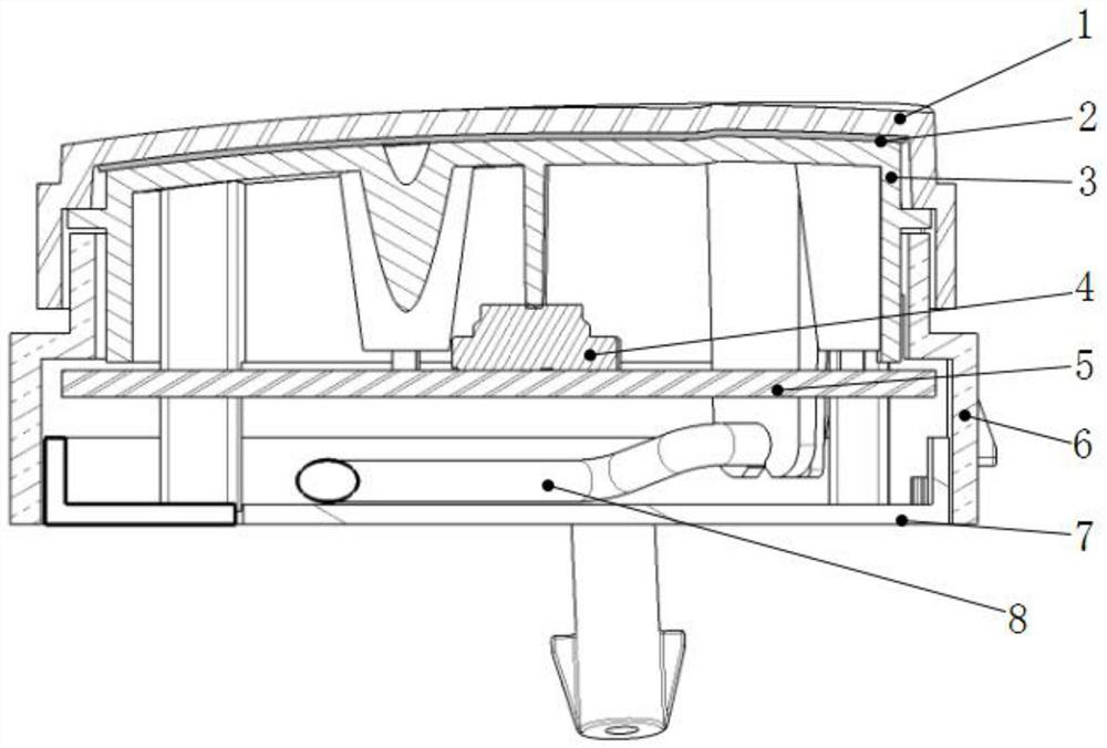
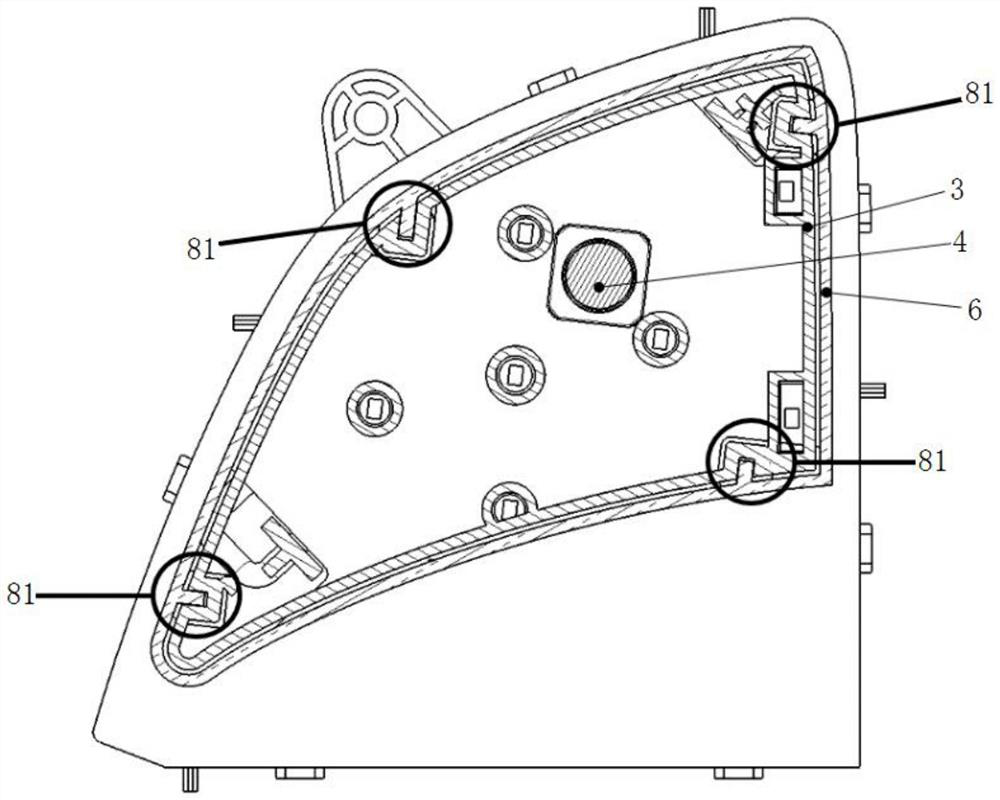
[0039] like Figure 4 As shown, a kind of anti-mistouch switch based on the Hall effect includes a panel 1, a middle casing 6 and a bottom casing 7; In the upper part, the sliding direction of the panel 1 is parallel to the up and down direction of the middle casing 6; the bottom casing 7 is installed on the lower part of the middle casing 6, and the middle casing 6 is provided with a PCBA5, and a Hall sensor 10 is installed on the PCBA5. A magnet 9 is installed on the panel 1 above the sensor 10 ; an elastic member 11 for resetting the panel 1 after being pressed is installed on the middle housing 6 .
[0040] pass Image 6 It can be seen that under different magnetic field strengths, the Hall sensor 10 will generate different voltage signals; Figure 5 As shown, the magnetic field is provided by the magnet 9, and the magnitude of the magnetic field is sensed by the Hall sensor 10. Therefore, when the user presses the panel 1 to cause displacement, the position of the magn...
Embodiment 2
[0048] It differs from Embodiment 1 in that: at least two Hall sensors 10 are installed at intervals on the PCBA5, such as Figure 7 As shown, correspondingly, a corresponding number of magnets 9 are installed on the panel 1 or the slider 3 .
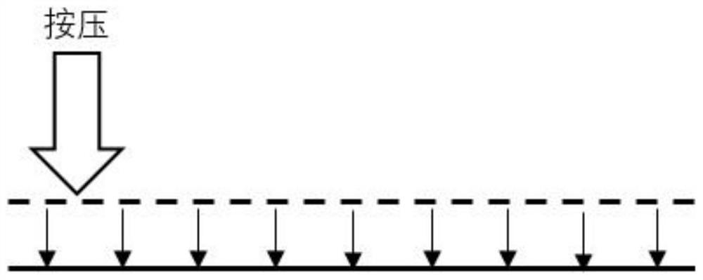
[0049] Such setting can solve the dead point problem of panel 1 movement. The combination of magnet 9 and Hall sensor 10 is arranged under the dead point of panel 1, and when the dead point is pressed, the Hall sensor 10 below the dead point can detect that the panel 1 is in motion. The small displacement of the dead point position (under the original micro switch scheme, in order to prevent multiple triggers from causing confusion, so only a single micro-motion strategy can be adopted, so pressing the dead point position of panel 1, the movement stroke of panel 1 is not enough to trigger micro switch); therefore, the present invention does not specifically limit the shape of the panel 1, which can effectively reduce the accuracy of the...
PUM
 Abstract
Description
Claims
Application Information
 - Generate Ideas
- Intellectual Property
- Life Sciences
- Materials
- Tech Scout
- Unparalleled Data Quality
- Higher Quality Content
- 60% Fewer Hallucinations
Browse by: Latest US Patents, China's latest patents, Technical Efficacy Thesaurus, Application Domain, Technology Topic, Popular Technical Reports.
© 2025 PatSnap. All rights reserved.Legal|Privacy policy|Modern Slavery Act Transparency Statement|Sitemap|About US| Contact US: help@patsnap.com


