Electrical automatic feeding device

An electrical automation, feeding device technology, applied in chemical instruments and methods, solid separation, sieves, etc., can solve the problems of screening and removal, reducing production efficiency and yield, affecting processing and production, etc.

Inactive Publication Date: 2020-10-23
JIANGSU MARITIME INST
View PDF0 Cites 2 Cited by
  • Summary
  • Abstract
  • Description
  • Claims
  • Application Information

AI Technical Summary

Problems solved by technology

[0004] The purpose of the present invention is to solve the shortcomings in the prior art, such as: the commonly used electric automatic feeding device cannot screen the conveyed materials

Method used


Image

  • Electrical automatic feeding device
  • Electrical automatic feeding device
  • Electrical automatic feeding device

Examples


Embodiment Construction

[0018] The following will clearly and completely describe the technical solutions in the embodiments of the present invention with reference to the accompanying drawings in the embodiments of the present invention. Obviously, the described embodiments are only some, not all, embodiments of the present invention.

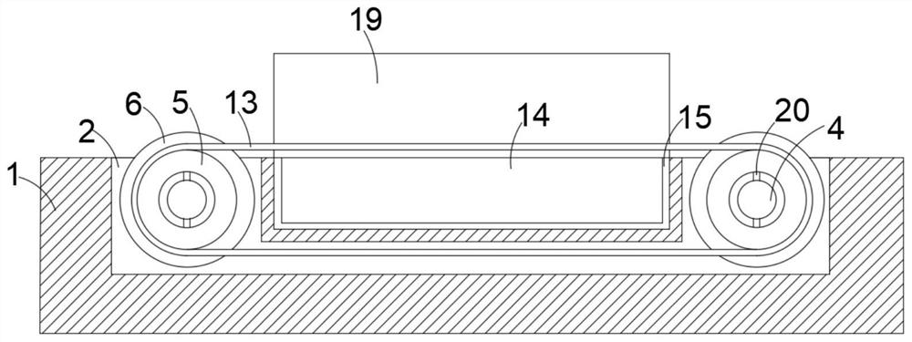
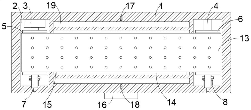
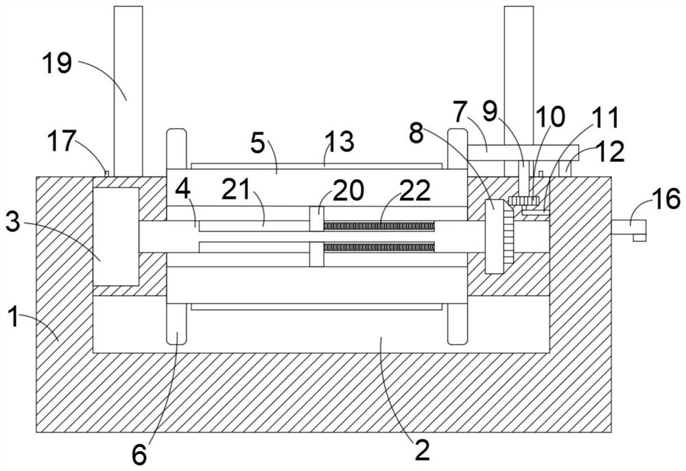
[0019] refer to Figure 1-5 , an electric automatic feeding device, comprising two drive rollers 5 arranged on a workbench 1, a U-shaped groove 2 is provided on the workbench 1, and two drive rollers 5 rotate longitudinally arranged on both sides of the U-shaped groove 2 In the groove, and the two drive rollers 5 are all rotated and arranged in the longitudinal groove of the U-shaped groove 2 by the rotating rod 4, and the side wall of the longitudinal groove on one side of the U-shaped groove 2 is fixedly provided with a motor 3, and the output end of the motor 3 It is fixedly connected with one end of the rotating rod 4 in the U-shaped groove 2 longitudinal grooves...


PUM


Abstract

The invention discloses an electrical automatic feeding device comprising two transmission rollers arranged on a workbench. The workbench is provided with a U-shaped groove, and the two transmission rollers are rotationally arranged in longitudinal grooves on the two sides of the U-shaped groove through rotating rods. A motor is fixedly arranged on the side wall of the longitudinal groove on one side of the U-shaped groove. The output end of the motor is fixedly connected with one end of each rotating rod located in the corresponding longitudinal groove of the U-shaped groove. The two rotatingrods are both provided with sliding mechanisms corresponding to the transmission rollers. The two ends of each transmission roller are both fixedly sleeved with annular plates. The workbench is provided with pushing mechanisms corresponding to the annular plates. The two transmission rollers are sleeved with a conveying belt. The electrical automatic feeding device can screen materials during feeding, screen out small materials and residues, guarantee the quality of conveyed materials and greatly facilitates follow-up machining of the materials.

Description

technical field [0001] The invention relates to the technical field of material conveying, in particular to an electric automatic feeding device. Background technique [0002] The electric automatic feeding device is a device for conveying materials. It is an indispensable equipment for both light industry and heavy industry. In the traditional concept, the feeding machine is a machine that uses the force of the machine movement to add force to the material and transport the material. With the continuous development of the times, electrical automation has gradually been applied to the feeding device, and the feeding equipment with a high degree of electrical automation includes moving head feeders controlled by computers, laser feeders, high-pressure air pressure and computer feeders, etc. Electric automation feeding The device can automatically complete the feeding, thus avoiding manual operation, greatly reducing the workload, and it is very safe. [0003] However, in the...

Claims


Application Information

Patent Timeline
IPC IPC(8): B07B1/10B07B1/46
CPCB07B1/10B07B1/46
Inventor 鲍秋燕
Owner JIANGSU MARITIME INST
Why Eureka
Try Eureka