Direction-adjustable sandy soil transfer device for highway construction

A transfer device and adjustable technology, applied in the direction of transportation and packaging, conveyors, mechanical conveyors, etc., can solve the problems of inability to transfer sand and the inability of the sand transfer device to rotate

Active Publication Date: 2020-10-20
合肥蓝川生态科技有限公司
View PDF5 Cites 1 Cited by
  • Summary
  • Abstract
  • Description
  • Claims
  • Application Information

AI Technical Summary

Problems solved by technology

[0005] In order to overcome the shortcomings of the current sand transfer device that cannot be rotated and cannot transfer sand in multiple directions during road construction, the technical problem of the present invention is to provide a rotatable, adjustable sand transfer device for road construction that can transfer sand in multiple directions. directional sand transfer device

Method used


Image

  • Direction-adjustable sandy soil transfer device for highway construction
  • Direction-adjustable sandy soil transfer device for highway construction
  • Direction-adjustable sandy soil transfer device for highway construction

Examples


Embodiment 1

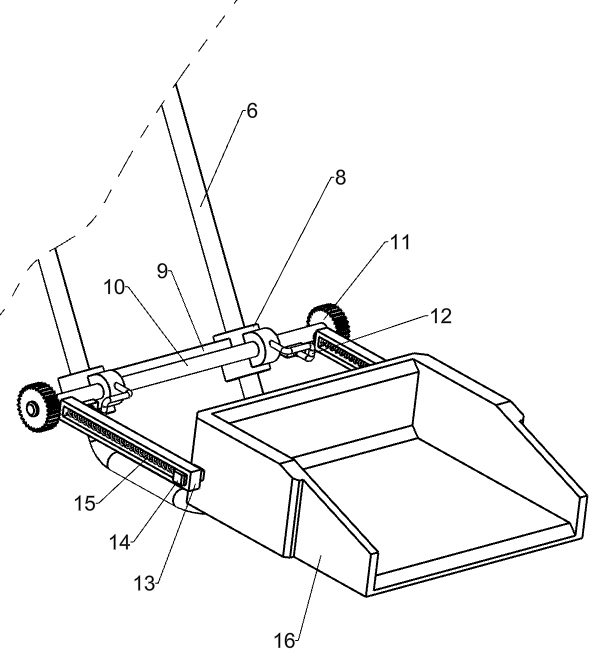
[0025] A sand transfer device with adjustable direction for road construction, such as Figure 1-5 As shown, it includes a bottom plate 1, a roller 2, a mounting frame 3, a guide assembly, a transfer assembly, and a drive assembly. The front and rear sides of the bottom plate 1 are symmetrically connected with the rollers 2 by bolts, and the middle part of the top of the bottom plate 1 is rotatably provided with a mounting frame. 3. The upper part of the installation frame 3 is provided with a guide assembly that guides the sand to flow into the transfer place, the front side of the guide assembly is provided with a transfer assembly that transfers the sand to the guide assembly, and the lower part of the installation frame 3 is provided with a motor to provide power to drive the transfer assembly to move drive components.

[0026] When using this device to transfer sand and soil, first pour the sand into the transfer assembly, then control the drive assembly to work, drive th...

Embodiment 2

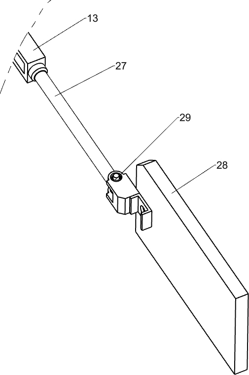
[0034] On the basis of Example 1, such as figure 1 , 6 , 7 and 8, also includes a wedge block 23, and the front side of the special-shaped rod 6 is fixedly connected with a wedge block 23 by bolts.

[0035] When the hopper 16 was positioned at the bottom of the special-shaped bar 6, the hopper 16 was pulled to the front side of the slide rail 13, and the position of the hopper 16 was fixed by the wedge block 23. At this moment, the first spring 15 was in a stretched state.

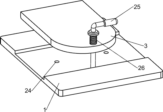
[0036]Also include a right-angle rod 25 and a second spring 26, four circular holes 24 are evenly spaced on the base plate 1, and the front side of the mounting frame 3 is slidingly provided with a right-angle rod 25, and the bottom of the right-angle rod 25 passes through the circular holes 24 , A second spring 26 is provided between the right-angle rod 25 and the mounting frame 3 .

[0037] When the sand in other directions needs to be transferred, the right-angle rod 25 can be pulled up, and the secon...


PUM


Abstract

The invention relates to a transfer device, in particular to a direction-adjustable sandy soil transfer device for highway construction. The technical problem to be solved by the invention is to provide the direction-adjustable sandy soil transfer device for highway construction, which is rotatable and can transfer sand in multiple directions. The direction-adjustable sandy soil transfer device for highway construction comprises a bottom plate, rollers, a mounting frame, a guide assembly, a transfer assembly and a driving assembly, wherein the rollers are symmetrically mounted on the bottom plate; the mounting frame is mounted on the bottom plate; the guide assembly is mounted on the mounting frame; the transfer assembly is mounted on the guide assembly; and the driving assembly is mountedon the mounting frame. According to the direction-adjustable sandy soil transfer device for highway construction, the driving assembly drives the transfer assembly to move, the transfer assembly is made to rotate on the front side of the guide assembly, sand in the transfer assembly falls into the guide assembly and flows to the transferring position through the guide assembly to complete transferring work of the sand, and due to the fact that the device can steer, the sand can be transferred in multiple directions.

Description

technical field [0001] The invention relates to a transfer device, in particular to a direction-adjustable sand transfer device for road construction. Background technique [0002] Highway is a modern term. It is a public road where cars can be driven. Many vehicles such as cars, bicycles, rickshaws, horses, and pedestrians can walk. There were no restrictions on the early roads, most of which were simple roads. Later, different roads had different restrictions; due to the increasingly developed traffic, more and more roads were used with restrictions, especially some roads were dedicated to cars, and expressways were developed. Type, designed for full-enclosed use in cars. [0003] The patent authorization notification number is CN207192082U, which discloses a sand transfer device for road construction, including a base, etc.; the top of the base is connected with a transfer mechanism, and the front side of the transfer mechanism is connected with a drive mechanism. The p...

Claims


Application Information

Patent Timeline
IPC IPC(8): B65G47/74B65G37/00
CPCB65G37/00B65G47/74
Inventor 李云飞
Owner 合肥蓝川生态科技有限公司
Why Eureka
Try Eureka