Adjustable building design working platform device
A technology for architectural design and working platform, which is applied to the legs of general furniture, extensible tables, tables that can change the height of the table top, etc.
- Summary
- Abstract
- Description
- Claims
- Application Information
AI Technical Summary
Problems solved by technology
Method used
Image
Examples
Embodiment 1
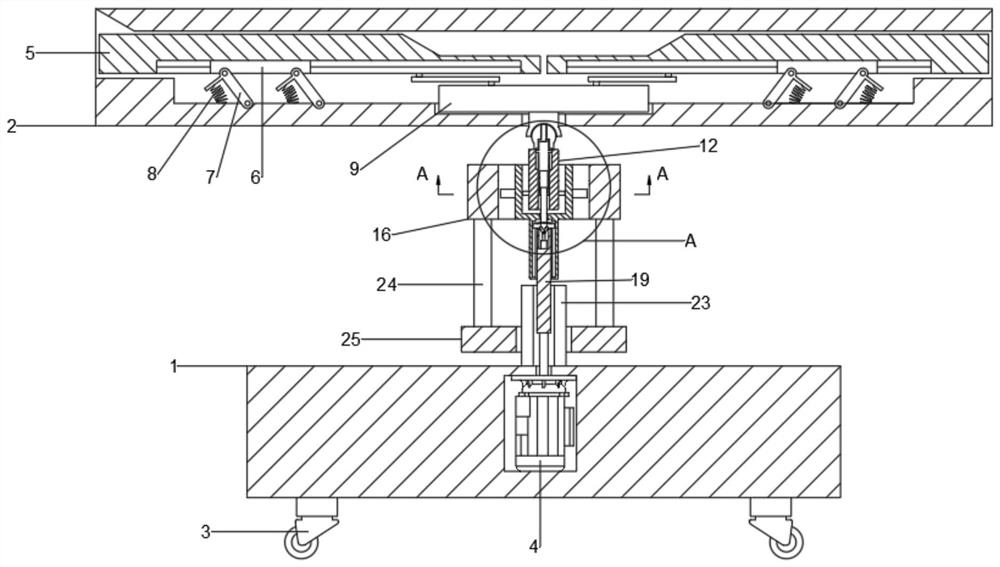
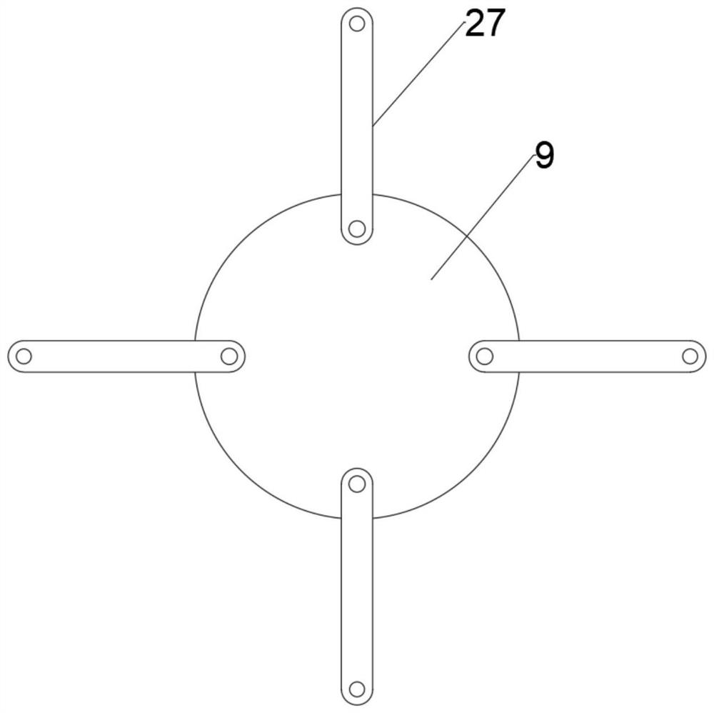
[0027] see Figure 1-5 , in an embodiment of the present invention, an adjustable architectural design work platform device includes a base 1 and a main workbench 2, and an auxiliary workbench 5 is installed symmetrically slidingly inside the main workbench 2, so that multiple people can work at the same time. A stretching mechanism is provided between the main workbench 2 and the auxiliary workbench 5, so as to realize the switching between single use and multi-person use of the workbench. The stretching mechanism includes a first turntable 9, and the first turntable 9 is rotatably mounted. In the main workbench 2, a connecting rod 27 is hinged between the first turntable 9 and the auxiliary workbench 5, and a chute is integrally formed on the auxiliary workbench 5, and a slider 6 is slidably installed in the chute. , a hinge bar 7 is hinged between the slider 6 and the main workbench 2, and a spring 8 is connected and fixed between one end of the hinge bar 7 and the main wor...
Embodiment 2
[0030] This embodiment is further improved on the basis of embodiment 1, and the content of the improvement is that universal wheels 3 are symmetrically installed and fixed on the lower surface of the base 1 to facilitate the movement of the entire workbench.
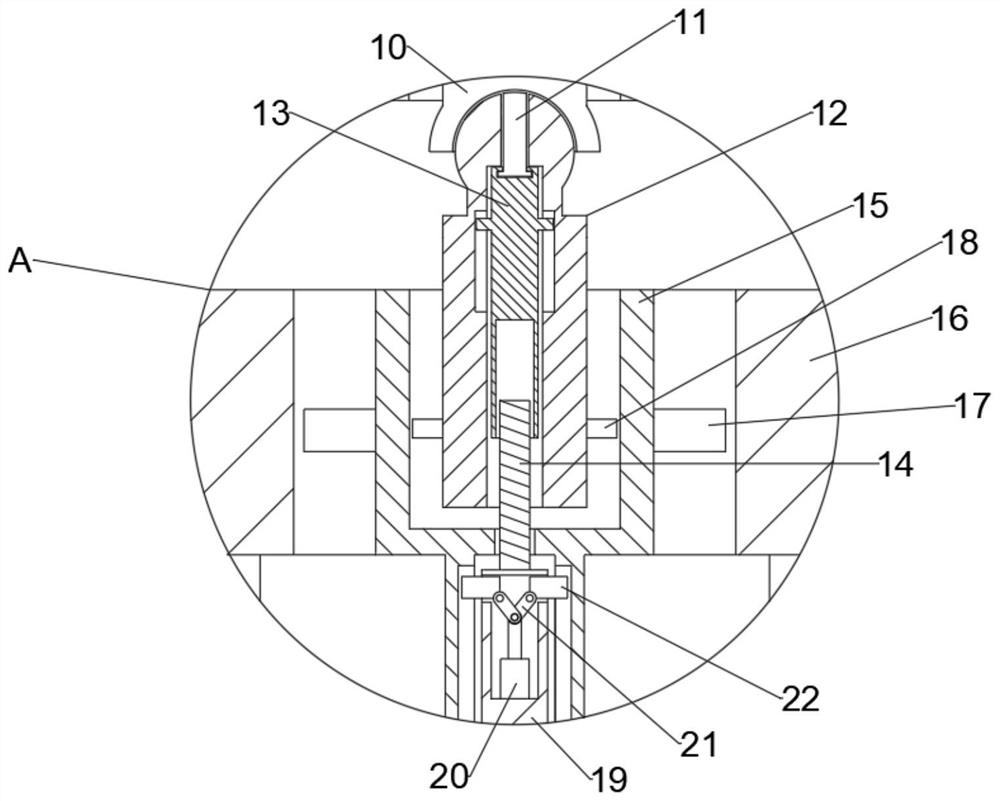
[0031] Further, because the traditional workbench cannot adjust the angle and cannot meet the posture requirements of different workers, in order to solve this problem, an angle adjustment mechanism is arranged inside the rotating shaft 12, and the angle adjustment mechanism includes a clip bar 11, Lifting rod 13 and threaded rod 14, described lifting rod 13 is slidably installed in the rotating shaft 12, and clamp bar 11 is installed in described lifting rod 13, and described clamping bar 11 runs through one end of rotating shaft 12 and is slidably connected with rotating shaft 12, so One end of the connecting shaft 10 is integrally formed with a card groove and an adjustment groove 26, the clip bar 11 is slidingly enga...
Embodiment 1
[0032] In conjunction with embodiment 1, embodiment 2, working principle of the present invention is:
[0033]When using the present invention, when the stepper motor 4 rotates clockwise, under the action of the rotating rod 19, the inner ratchet shaft 15 is driven to rotate clockwise, and under the action of the second ratchet card 18, the rotating shaft 12 is driven to rotate, thereby driving The first turntable 9 rotates, and under the action of the connecting rod 27, the auxiliary workbench 5 is driven to slide around the main workbench 2. When the auxiliary workbench 5 slides to the limit distance, under the action of the hinge rod 7 and the spring 8, As a result, the auxiliary workbench 5 is pushed upwards, so that the auxiliary workbench 5 and the main workbench 2 maintain the same horizontal plane; when the stepping motor 4 rotates counterclockwise, the outer ratchet shaft 16 is driven to rotate by the first ratchet card 17 , through the action of the support column 24...
PUM
 Abstract
Description
Claims
Application Information
 - R&D Engineer
- R&D Manager
- IP Professional
- Industry Leading Data Capabilities
- Powerful AI technology
- Patent DNA Extraction
Browse by: Latest US Patents, China's latest patents, Technical Efficacy Thesaurus, Application Domain, Technology Topic, Popular Technical Reports.
© 2024 PatSnap. All rights reserved.Legal|Privacy policy|Modern Slavery Act Transparency Statement|Sitemap|About US| Contact US: help@patsnap.com


