Charging control device and method

A charging control and waiting-to-charge technology, applied in circuit devices, battery circuit devices, current collectors, etc., can solve the problem of a single charging method, and achieve high charging power and flexible charging methods.

Active Publication Date: 2020-10-02
LENOVO (BEIJING) LTD
View PDF5 Cites 2 Cited by
  • Summary
  • Abstract
  • Description
  • Claims
  • Application Information

AI Technical Summary

Problems solved by technology

[0004] In view of this, the present application provides a charging control device to solve the problem of single charging method in the prior art

Method used


Image

  • Charging control device and method
  • Charging control device and method
  • Charging control device and method

Examples


Embodiment Construction

[0049] The following will clearly and completely describe the technical solutions in the embodiments of the application with reference to the drawings in the embodiments of the application. Apparently, the described embodiments are only some of the embodiments of the application, not all of them. Based on the embodiments in this application, all other embodiments obtained by persons of ordinary skill in the art without making creative efforts belong to the scope of protection of this application.

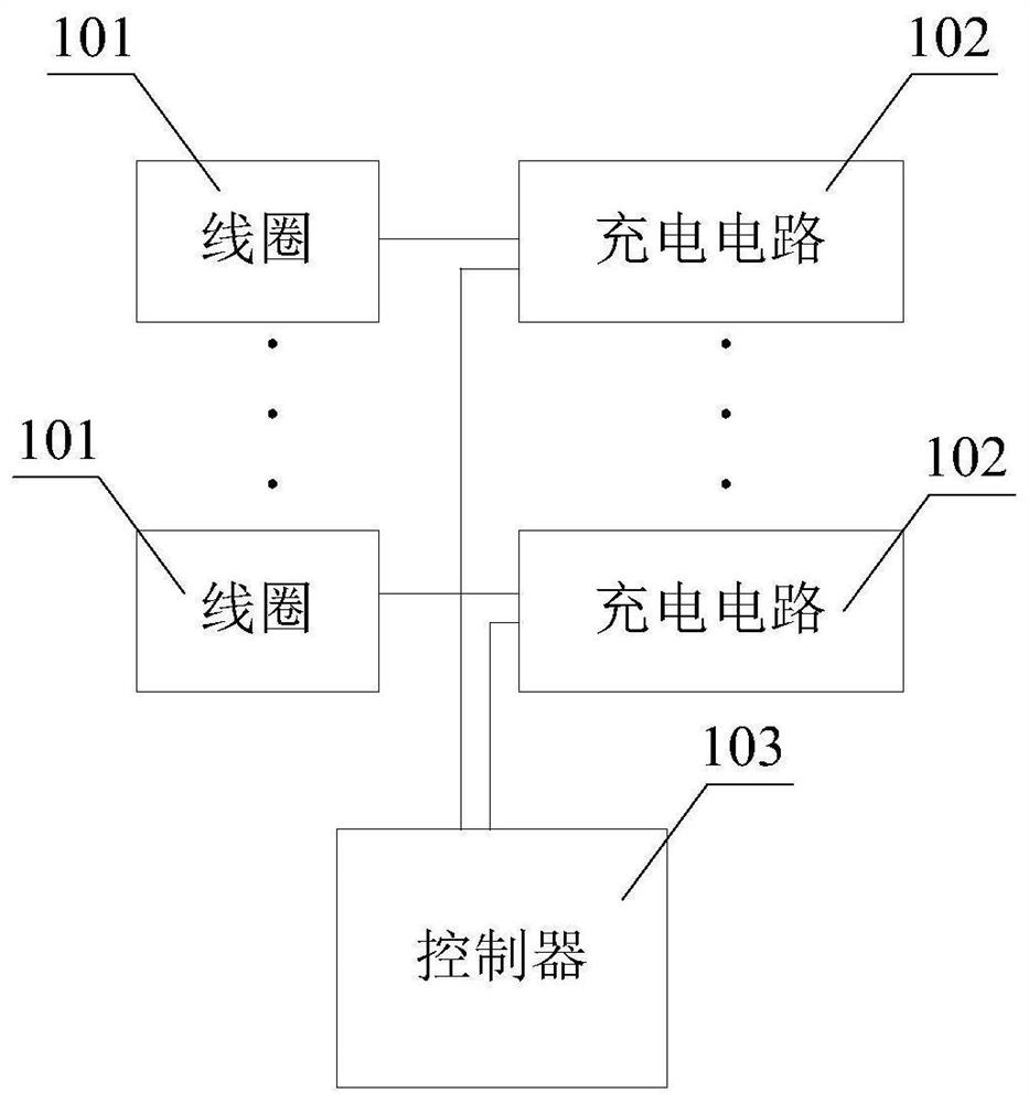
[0050] Such as figure 1 Shown is a schematic structural diagram of Embodiment 1 of a charging control device provided in the present application, including: at least M parallel coils 101, at least M parallel charging circuits 102, and a controller 103; figure 1 2 coils are used to indicate the M coils, and correspondingly, 2 charging circuits are used to indicate the M charging circuits.

[0051] Wherein, M is an integer greater than or equal to 2.

[0052] Wherein, any one of the...


PUM


Abstract

The invention provides a charging control device, which comprises at least M coils connected in parallel, at least M charging circuits connected in parallel and in one-to-one correspondence with the Mcoils and a controller, wherein any one coil can be coupled with a coil of charging end equipment so as to receive charging electric energy provided by the charging end equipment, and M is an integergreater than or equal to 2; the controller is connected with the M coils connected in parallel and the charging circuit and used for selecting N coils from the M coils, M is larger than or equal to N, and N is an integer larger than or equal to 1; the N coils are controlled to receive charging electric energy provided by the charging end equipment; and N charging circuits in one-to-one correspondence with the N coils are controlled to charge the to-be-charged end equipment according to the charging electric energy. In the scheme, the plurality of coils are arranged in the to-be-charged end equipment in parallel, one or more coils are selected during charging, the charging power of the to-be-charged end equipment can be diversified, the charging mode is more flexible, and when the plurality of coils connected in parallel are used for receiving the charging electric energy provided by the charging end equipment, higher charging power can be received.

Description

technical field [0001] The present application relates to the field of electronic equipment, and more specifically, to a charging control device and method. Background technique [0002] With the development of electronic technology, wireless charging technology (Wireless charging technology) is widely used in various charging fields. [0003] In the prior art, an electronic device is provided with a coil, which is coupled with the coil of the charging terminal device, so as to realize the process of wireless charging. However, during the charging process, due to the limit of the temperature rise of the coil, the limit current that the coil can withstand is constant, so the charging power of the electronic device is also limited within a certain value, and the charging method is single. Contents of the invention [0004] In view of this, the present application provides a charging control device to solve the problem of a single charging method in the prior art. [0005] ...

Claims


Application Information

Patent Timeline
Patent Type & Authority Applications(China)
IPC IPC(8): H02J7/00H02J50/20H02J50/40H02J50/80H02J50/90
CPCH02J7/0029H02J50/20H02J50/40H02J50/80H02J50/90
Inventor 佟宇飞刘和生
Owner LENOVO (BEIJING) LTD
Why Eureka
Try Eureka