Portable medical protective garment

A protective clothing and portable technology, applied in protective clothing, clothing, clothing, etc., can solve the problems of airway water shortage, unfavorable work of medical staff, dry hair, etc., and achieve the effect of alleviating dry mouth and reducing the burden of carrying

Active Publication Date: 2020-09-29
HENAN YADU IND
View PDF15 Cites 2 Cited by
  • Summary
  • Abstract
  • Description
  • Claims
  • Application Information

AI Technical Summary

Problems solved by technology

[0003] When medical personnel work in an area with a high degree of protection, they usually wear a fully enclosed protective suit, and the gas supply device is an indispensable part of the fully enclosed protective suit, which is used to provide protection from external polluted gases. It can breathe clean air and maintain a certain pressure inside the protective clothing. Although some protective clothing has external air supply protective equipment, the external air supply equipment is often cumbersome. When medical staff go to the workplace, they need to put the protective clothing, air supply The equipment is first transferred to the workplace, and then worn. During the transfer process, it needs to be transferred by hand. In addition, the medical staff also need to carry other medical equipment, which brings a greater burden to the medical staff. It is not conducive to the normal medical work of medical staff;
[0004] The existing one-piece protective clothing will consume a lot of water when the medical staff work for a long time. In addition to the inconvenience of wearing the one-piece protective clothing, most medical staff will reduce drinking water or stop drinking water to reduce the need to go to the toilet. As a result, the throat and airway of the medical staff will be dry due to lack of water, which will cause discomfort to the medical staff, which is not conducive to the work of the medical staff;

Method used


Image

  • Portable medical protective garment
  • Portable medical protective garment
  • Portable medical protective garment

Examples


Embodiment 1

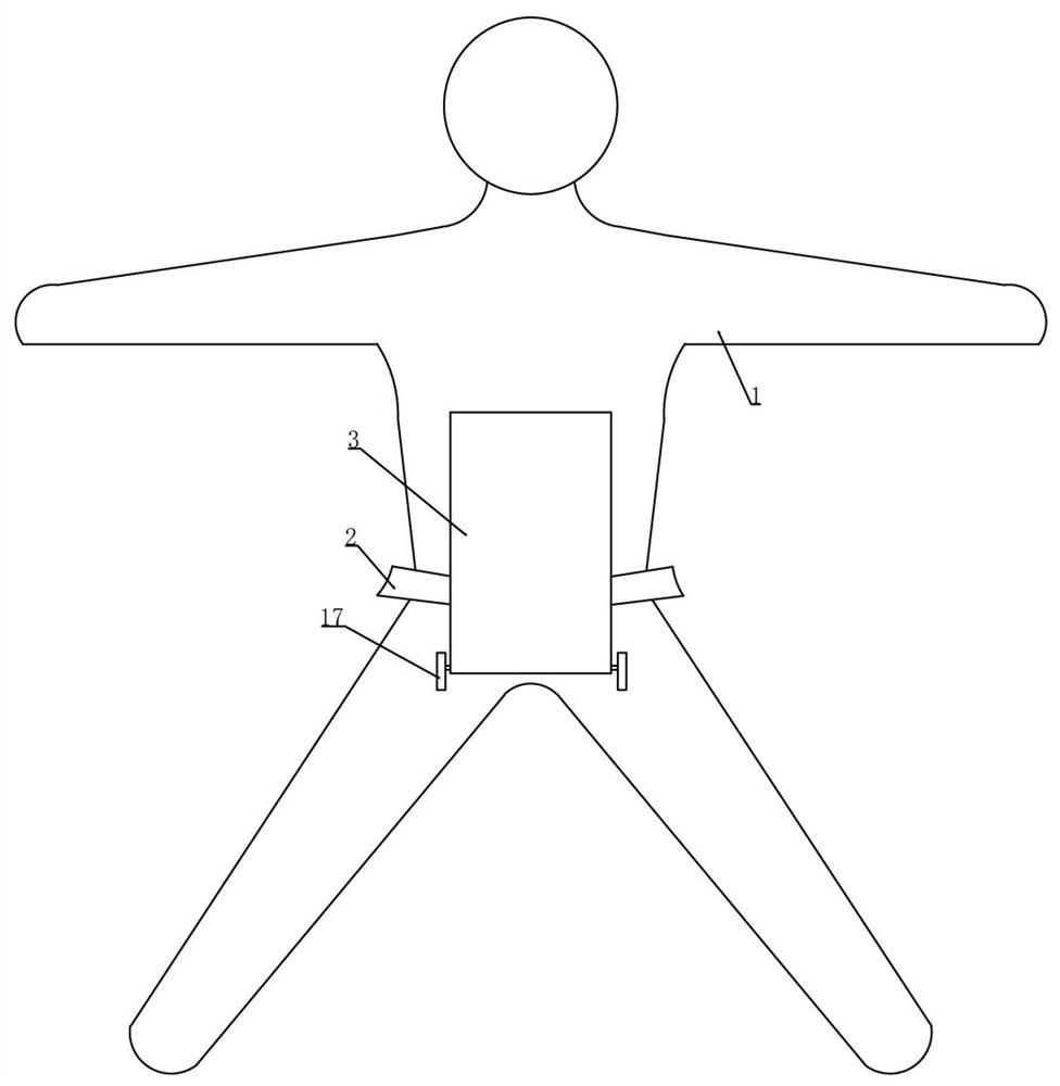
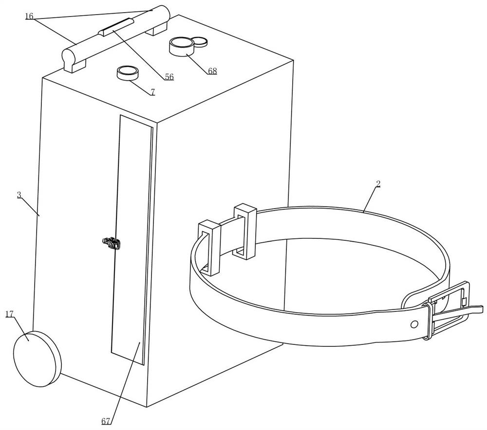
[0044] Embodiment 1, this embodiment provides a kind of portable medical protective clothing 1, refer to the attached figure 1 As shown, it includes a protective clothing 1 (the protective clothing 1 is an integrated fully enclosed protective clothing 1), which is characterized in that we disassemble and install a belt 2 on the waist of the protective clothing 1. When the medical staff puts on the protective clothing 1, Use the belt 2 to fix the equipment box 3 at the waist of the body. Figure 6 As shown, the equipment box 3 is divided into an equipment cavity 5 and a storage cavity 6 (the storage cavity 6 is used to place protective clothing 1 and other items, refer to the attached figure 2 As shown, we rotate and install the door panel 67 on the equipment box 3 and position the door panel 67 on the equipment box 3 through the lock). Deliver the outside air to the upper end of the protective clothing 1 (the reason why the detachable hose is connected with the upper end of ...

Embodiment 2

[0051] Embodiment 2, on the basis of embodiment 1, with reference to appended Figure 7 As shown, the air supply device includes a disinfecting box 18 installed in the equipment cavity 5 and the disinfecting box 18 communicates with the outside world. We rotate and install fan blades 19 in the disinfecting box 18 and the fan blades 19 are fixedly installed in the disinfecting box 18. The motor 20 on the inner wall of the killing box 18 is driven (the motor 20 is provided with electric energy provided by the storage battery in the equipment box 3). For the effect of transporting the outside air to the protective clothing 1, we have installed ultraviolet lamps 21 on the lateral side walls of the disinfecting box 18 and several ultraviolet lamps 21 are connected in series in the electric circuit of the motor 20. When the motor 20 starts to work, several The ultraviolet light 21 lights up synchronously and realizes that the outside air entering into the killing box 18 is disinfected ...

Embodiment 3

[0053] Embodiment 3, on the basis of embodiment 1, with reference to appended Figure 12 As shown, the positioning device includes: the opposite sides of the two guide tubes 11 are respectively slidably installed with positioning columns 22 (refer to the attached Figure 9 As shown, we fixed a triangular rod on the outer end of the positioning post 22 placed on the guide tube 11 and fixed a triangular tube slidingly fitted with the triangular rod on the outer wall of the wetting tube 68, so as to realize the positioning of the positioning post 22), refer to the attached Figure 9 As shown, the positioning column 22 is placed on the outer end of the guide tube 11 and is integrally connected with an L-shaped rod 23, referring to the attached Figure 12 As shown, we put the positioning column 22 in the guide tube 11 and set the rounded corners at one end, refer to the attached Figure 13 As shown, we set a round hole 71 on the outer wall of the opposite side of the upper ends of...


PUM


Abstract

The invention relates to a portable medical protective garment, and effectively solves the problem that the existing protective garment and accessory equipment thereof are more, so that medical personnel are inconvenient to carry during transition work. The technical scheme is characterized in that a protective garment is provided with air supply equipment box, and external fresh air can be fed into the protective garment through the air supply equipment box, and dirty and humid air in the protective garment can be exhausted outwards through the air supply equipment box. Medical staff can select to convey dry air flow or normal air flow into the protective garment according to conditions. When transition movement needs to be conducted, the protective garment can be placed in the air supplyequipment box and pulled by the U-shaped pull rod to move, and the carrying burden of the medical staff is greatly reduced.

Description

technical field [0001] The invention relates to the technical field of medical protection, in particular to a portable medical protective clothing. Background technique [0002] Medical protective clothing refers to the protective clothing used by medical personnel (doctors, nurses, public health personnel, cleaning personnel, etc.) and people entering specific medical and health areas (such as patients, hospital visitors, personnel entering infected areas, etc.), Its function is to isolate germs, harmful ultrafine dust, acid-base solution, electromagnetic radiation, etc., to ensure the safety of personnel and keep the environment clean; [0003] When medical personnel work in an area with a high degree of protection, they usually wear a fully enclosed protective suit, and the gas supply device is an indispensable part of the fully enclosed protective suit, which is used to provide protection from external polluted gases. It can breathe clean air and maintain a certain pres...

Claims


Application Information

Patent Timeline
IPC IPC(8): A41D13/12A41D13/002A41D27/00A62B7/12A62B17/00A62B18/02H02K7/18H02K1/17H02K1/22
CPCA41D13/12A41D13/0025A41D27/00A62B7/12A62B17/00A62B18/02H02K7/1846H02K1/17H02K1/22
Inventor 韩立涛段书霞韩涵佘开江殷苏明付迎坤韩修恒韩伟鹤潘洪福林建香段玉堂赵欣王蓉徐玉茵范頔闫钧高文静张丹丹陈玮雯柳小军田林奇周静崔彬彬陈琳朱政辉魏峥琦李夏
Owner HENAN YADU IND
Why Eureka
Try Eureka