Method for adjusting coupling waveguide ring of resonant cavity, adjusting device and resonant cavity

A technology of coupling waveguide and adjustment method, which is applied in the field of resonant cavity, and can solve the problem that the coupled waveguide ring cannot be adjusted automatically

Active Publication Date: 2022-02-08
迈谱新材料技术(山东)有限公司
View PDF10 Cites 0 Cited by
  • Summary
  • Abstract
  • Description
  • Claims
  • Application Information

AI Technical Summary

Problems solved by technology

[0006] The main purpose of this application is to provide an adjustment method, an adjustment device, a computer-readable storage medium, a processor and a resonant cavity for a coupling waveguide ring of a resonant cavity, so as to solve the problem that the coupling waveguide ring cannot be automatically adjusted in the prior art

Method used


Image

  • Method for adjusting coupling waveguide ring of resonant cavity, adjusting device and resonant cavity
  • Method for adjusting coupling waveguide ring of resonant cavity, adjusting device and resonant cavity
  • Method for adjusting coupling waveguide ring of resonant cavity, adjusting device and resonant cavity

Examples


Embodiment

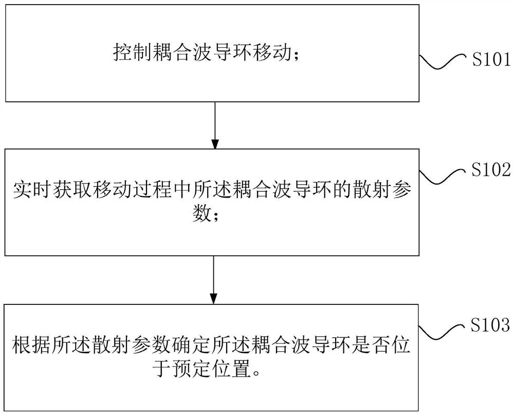
[0060] Such as image 3 As shown, the application scenario of the method for adjusting the coupling waveguide ring in this embodiment includes the coupling waveguide ring 100, the potentiometer 200, the position information acquisition device 300, the network analyzer 400, the driver 500 and the servo motor 600, which are electrically connected in sequence. 600 is a high-resolution motor, and the driver 500 is a driver corresponding to the high-resolution motor.

[0061] The process of implementing the adjustment method of the coupling waveguide ring in the above application scenario includes the following steps: the potentiometer 200 converts the position signal of the coupling waveguide ring 100 into an electrical signal and transmits it to the position information collection device 300, and the position information collection device 300 converts the coupling waveguide ring The position information of 100 is transmitted to the network analyzer 400, and the network analyzer 4...


PUM


Abstract

The present application provides a method for adjusting a coupling waveguide ring of a resonant cavity, an adjusting device and a resonant cavity. The adjustment method includes: controlling the movement of the coupling waveguide ring; acquiring the scattering parameters of the coupling waveguide ring during the moving process in real time; and determining whether the coupling waveguide ring is at a predetermined position according to the scattering parameters. The above method detects the scattering parameters of the coupling waveguide ring during the movement of the coupling waveguide ring to determine whether the coupling waveguide ring is at a predetermined position, and controls the coupling waveguide ring to stop moving when the coupling waveguide ring is at a predetermined position. Adjustment, the entire adjustment process does not need manual adjustment, and the automatic adjustment of the coupling waveguide ring is realized.

Description

technical field [0001] The present application relates to the technical field of resonant cavities, and in particular, relates to a method for adjusting a coupling waveguide ring of a resonant cavity, an adjusting device, a computer-readable storage medium, a processor and a resonant cavity. Background technique [0002] According to the principle, the testing methods of dielectric material properties can be divided into two categories: network parameter method and resonant cavity method. In comparison, the network parameter method is suitable for testing materials with higher dielectric loss, while materials with lower dielectric loss are usually tested by resonant cavity method. Resonator methods usually include high-Q cavity method, resonator perturbation method, stripline resonator method, superconducting cavity method, rectangular dielectric material surface metallization resonance method, and dielectric resonator method. Among them, the separated dielectric resonator ...

Claims


Application Information

Patent Timeline
Patent Type & Authority Patents(China)
IPC IPC(8): H01P5/12H01P7/06
CPCH01P5/12H01P7/06
Inventor 宋锡滨杨宏伟奚洪亮艾辽东鞠云忠
Owner 迈谱新材料技术(山东)有限公司
Why Eureka
Try Eureka