


Quick Research
Generate reliable direction feasibility study reports for your R&D in just a few steps.

Technical Q&A
Discover and master advanced knowledge NOW. Basics, ideas, possibilities, all at once.

Find Solutions
As an expert in R&D theories, this can generate solutions to your technical problems instantly.

Evaluate Feasibility
Analyze your overall solution with one click, know your potential R&D risks in advance.

Monitor Landscape
Get weekly tech updates, stay abreast of the latest tech innovations and key insights.
Protection type unpowered roller conveying line
A conveyor line and roller technology, applied in the field of protective unpowered roller conveyor lines, can solve the problems of falling and the plate is easy to continue to move forward, and achieve the effect of improving stability
- Summary
- Abstract
- Description
- Claims
- Application Information
AI Technical Summary
Problems solved by technology
Method used
Image

Examples
Embodiment 1
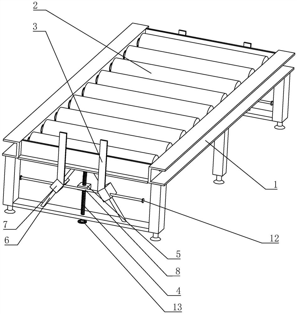
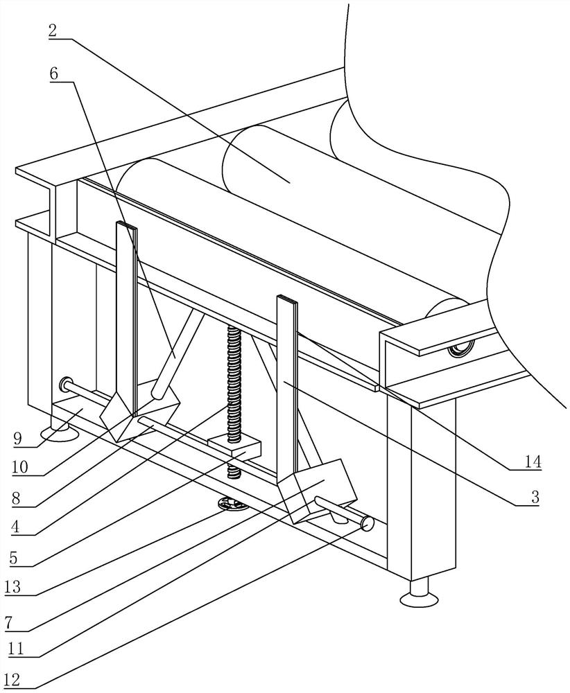
[0041] Embodiment 1: refer to figure 1 , is a protective unpowered roller conveyor line disclosed in the present invention, including a bracket 1, a roller 2 and a protective device, the roller 2 is rotatably connected to the bracket 1, the protective device is arranged at both ends of the bracket 1, and the protective device includes a baffle 3 and a lifting mechanism for driving the baffle plate 3 to move up and down, the lifting mechanism is arranged on the support 1, and the baffle plate 3 is arranged on the lifting part of the lifting mechanism so as to move together with the lifting part of the lifting mechanism.
[0042] refer to figure 1 and figure 2 , The lifting mechanism includes a screw mandrel 4, a nut block 5, an inclined rod 6, a sliding block 7 and a linkage rod 8.
[0043] refer to figure 1 and figure 2 , the bracket 1 is welded with a first support plate 9, one end of the screw rod 4 is rotatably connected with the bracket 1, and the other end is rotata...
Embodiment 2
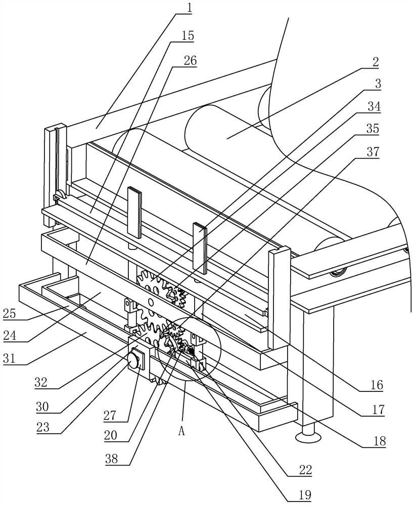
[0045] Embodiment 2: refer to image 3 and Figure 4 , The difference from Embodiment 1 is that the lifting mechanism includes a lifting plate 15, a fixed plate 16, a guide rod 17, a hinge rod 18, a connecting rod 19, a connecting piece 20, a first rotating shaft 21, a second rotating shaft 22 and a second rotating shaft. hand wheel 23.
[0046] refer to image 3 and Figure 5 , the first rotating shaft 21 and the second rotating shaft 22 are rotatably connected with the bracket 1, the bracket 1 is welded with a second support plate 24, and the second support plate 24 is welded with a first U-shaped frame 25 and a second U-shaped frame 26, The second rotating shaft 22 is rotationally connected with the second support plate 24, the first rotating shaft 21 is rotationally connected with the first U-shaped frame 25 and runs through the first U-shaped frame 25, the centerline of the first rotating shaft 21 and the centerline of the second rotating shaft 22 overlap, and there i...
PUM
 Abstract
Description
Claims
Application Information
 - R&D Engineer
- R&D Manager
- IP Professional
- Industry Leading Data Capabilities
- Powerful AI technology
- Patent DNA Extraction
Browse by: Latest US Patents, China's latest patents, Technical Efficacy Thesaurus, Application Domain, Technology Topic, Popular Technical Reports.
© 2024 PatSnap. All rights reserved.Legal|Privacy policy|Modern Slavery Act Transparency Statement|Sitemap|About US| Contact US: help@patsnap.com