
Distributing mechanism for workshop conveyor

A material distribution mechanism and conveyor technology, which is applied in the direction of separating solids from solids by air flow, solid separation, and sieving, etc., can solve the problems of low screening efficiency, easy blockage, and affecting the normal operation of the material distribution mechanism. , to achieve the effect of simple structure, prevention of blockage and high degree of automation

Inactive Publication Date: 2020-09-18
合肥森印科技有限公司
View PDF0 Cites 7 Cited by
  • Summary
  • Abstract
  • Description
  • Claims
  • Application Information

AI Technical Summary

Problems solved by technology

[0004] The object of the present invention is to provide a material distribution mechanism for workshop conveyors, through the design of rings, arc-shaped sieve plates, shafts, booms, sweeping plates and material distribution hoppers, it solves the problem of the existing vibrating screen type. The screening efficiency of the feeding mechanism is low, and it is prone to blockage, which affects the normal operation of the feeding mechanism

Method used

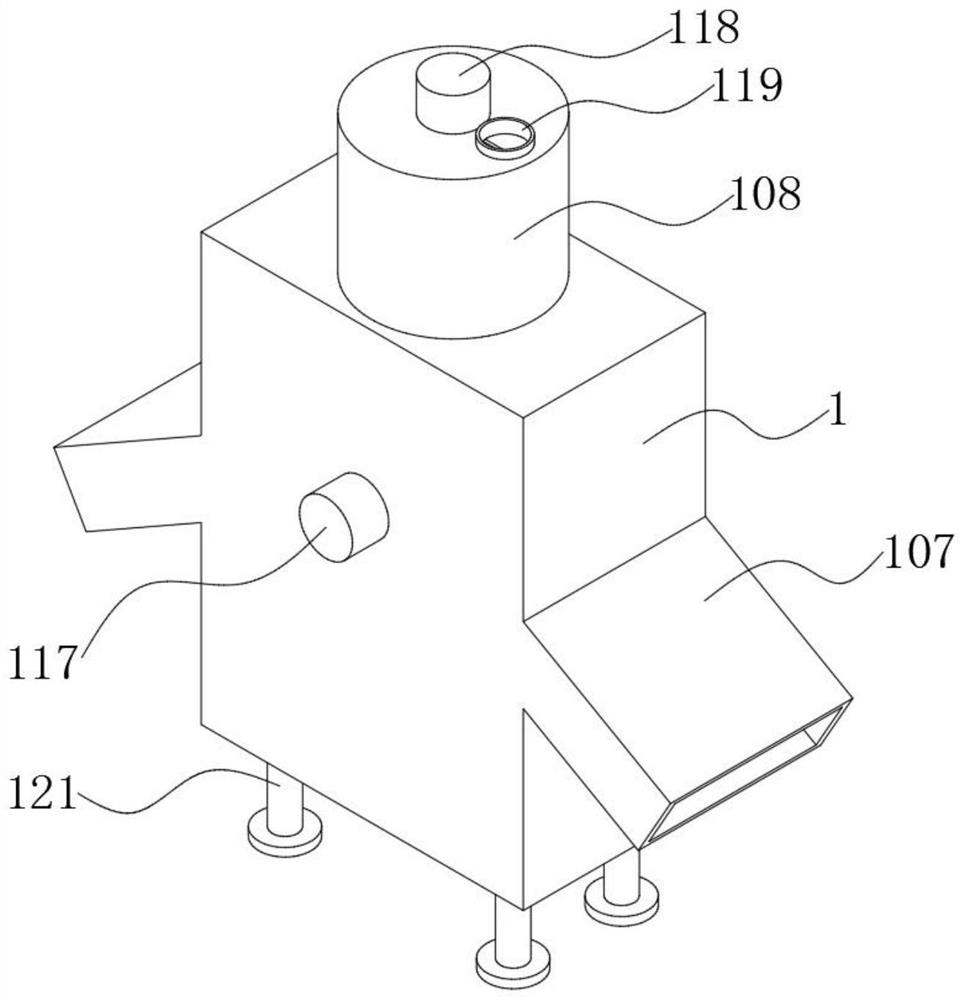
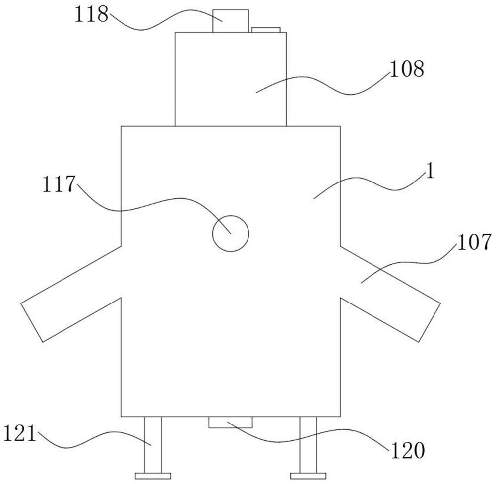
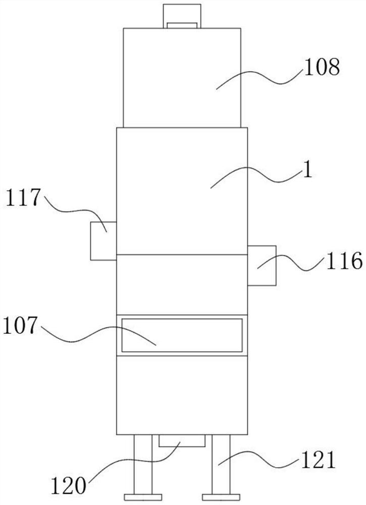

Image

  • Distributing mechanism for workshop conveyor
  • Distributing mechanism for workshop conveyor
  • Distributing mechanism for workshop conveyor

Examples


Embodiment Construction

[0028] The following will clearly and completely describe the technical solutions in the embodiments of the present invention with reference to the accompanying drawings in the embodiments of the present invention. Obviously, the described embodiments are only some, not all, embodiments of the present invention. Based on the embodiments of the present invention, all other embodiments obtained by persons of ordinary skill in the art without creative efforts fall within the protection scope of the present invention.

[0029] see Figure 1-6 , the present invention is a material distributing mechanism for a workshop conveyor, comprising a material distributing box 1;

[0030] The inner side wall of the distribution box 1 is connected with a circular ring 101 through bearing rotation, and a plurality of connecting rods 102 are fixedly connected to the side of the circular ring 101, and one end of the connecting rod 102 is fixedly connected with an arc-shaped sieve plate 103, and t...


PUM


Abstract

The invention discloses a distributing mechanism for a workshop conveyor, and relates to the technical field of workshop conveying equipment. The distributing mechanism comprises a distribution box, wherein a circular ring is rotationally connected to one inner side wall of the distribution box through a bearing, a plurality of connecting rods are fixedly connected to the circumferential side faceof the circular ring, an arc-shaped sieve plate is fixedly connected to one end of each of the connecting rods, a shaft rod is rotationally connected between the two opposite inner side walls of thedistribution box, a hanging rod is fixedly connected to the circumferential side face of the shaft rod, the lower end of the hanging rod is fixedly connected with a sweeping plate, and two distributing hoppers are symmetrically arranged on the other two opposite inner side walls of the distribution box and located below the two sides of the arc-shaped sieve plate. Through the design of the circular ring, the arc-shaped sieve plate, the shaft rod, the hanging rod, the sweeping plate and the distributing hoppers, the arc-shaped sieve plate is prevented from being blocked, the structure is simple, the automation degree is high, the screening efficiency of the distributing mechanism is improved, and the problems that an existing vibrating screen type distributing mechanism is low in screeningefficiency and prone to being blocked, and normal operation of the distributing mechanism is affected are solved.

Description

technical field [0001] The invention belongs to the technical field of workshop conveying equipment, and in particular relates to a material distributing mechanism for a workshop conveyor. Background technique [0002] For granular materials that need to be packaged separately or installed into products, in the production process, the granular material distribution mechanism is usually used to distribute the granular materials to realize feeding one by one. Biomass pellet fuel is a kind of renewable new energy. It is made of plant waste such as wood chips, tree branches, corn stalks, rice husks, etc., and is finally made into pellets through crushing, mixing, extrusion, drying and other processes. The fuel is directly burned as fuel. When further classifying the final granular fuel, it is often necessary to screen and classify it to sort out large-diameter particles with higher calorific value or particles with similar uniformity. The vibrating screen is the fastest-growing...

Claims


Application Information

Patent Timeline
Patent Type & Authority Applications(China)
IPC IPC(8): B07B1/34B07B1/42B07B1/46B07B1/24B07B1/52B07B9/00B02C13/18B02C13/284
CPCB02C13/18B02C13/284B07B1/24B07B1/343B07B1/42B07B1/46B07B1/52B07B9/00
Inventor 余小兵
Owner 合肥森印科技有限公司
Learn More